24 channel tube summing amplifier

GroupDIY Audio Forum

Help Support GroupDIY Audio Forum:

This site may earn a commission from merchant affiliate links, including eBay, Amazon, and others.

Holger

Well-known member
GDIY Supporter
Joined
Jun 11, 2006
Messages
893
Location
Hamburg, Germany
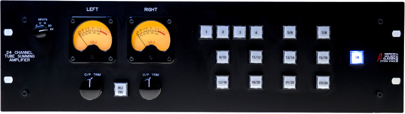
I've recently finished another good sounding tube project, a summing amplifier.
The amp section is Ian's TLA.

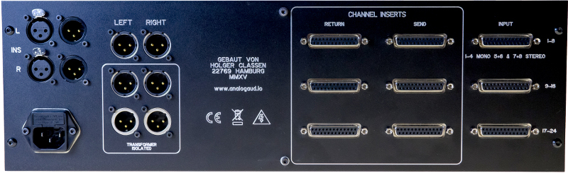
- 24 inputs on D-Sub (Tascam pinout), 1-4 mono, 5- 24 stereo
- inserts on every channel, D-Sub, Tascam pinout
- master insert
- three L/R outputs, two transformer isolated (utilizing Lundahl 1581XL)
- 1k output trim, Lorlin
- shunt resistor selector for correct impedance / connected inputs
tusufrontalscaled.jpg


tusurearscaled.jpg
 
That's awesome Holger. Like all your stuff.  Are there any similarities in sound to your console?  Is it comparable?  I believe you used Carnhills for the mixer and im sure that must have an effect? 
I've been seriously considering ditching my console for a summing amp very much like what you have done here so i would appreciate your thoughts.
 
Rocinante said:
...Are there any similarities in sound to your console?  Is it comparable?...
Honsestly, I haven't heard the console for a long time.

In the console each signal passes a transformer and a couple of tubes, in a summing amp the sum of all signals pass a transformer and some tubes.
There are similarities to some degree, but a simple summing device is not the same as a fully featured console.

I would describe the summing amp clean and wide and open. Try it, you won't regret it.
 
Summing amp becomes a thing of beauty! What did you choose for input and output transformers?

Regards,

Pierre
 
I really like the idea of switching the bus slugging resistor depending on the number of inputs connected. If you use TRS inputs this is not a problem as you can use switched contacts on the TRS socket to short unused inputs, but there is no way to do this using a DB25 input. Nice idea Holger.

Cheers

Ian
 
Very nice

Are your insert sends hard wired in?  The returns hard wired in?  I didn't see any switches, so they must be wired as on and in?  You simply connect to them or not with the DB25 cables? Is that the plan?

I didn't catch Ian's point about slugging the unused inputs.  Do you have switches that are shorting the inputs when not in use?  What is the point of that?  This must be your shunt resistor for correct impedance and the buttons we see.  Can you elaborate, please?
 
tommypiper said:
I didn't catch Ian's point about slugging the unused inputs.  Do you have switches that are shorting the inputs when not in use?  What is the point of that?  This must be your shunt resistor for correct impedance and the buttons we see.  Can you elaborate, please?

The value of the slugging resistor required depends on how many inputs are connected. Holger has a switch for this. It just alters the value of the slugging resistor. You don't have to do anything to the inputs.

Cheers

Ian
 
ruffrecords said:
The value of the slugging resistor required depends on how many inputs are connected. Holger has a switch for this. It just alters the value of the slugging resistor. You don't have to do anything to the inputs.

Cheers

Ian

Ian, thanks.  Those white push buttons?  Are they cummulatively changing the resistor values when you press for each channel?  Or  is there a master in/out switch adding a resistor somewhere...  sorry i don't quite  get it. 
 
tommypiper said:
Ian, thanks.  Those white push buttons?  Are they cummulatively changing the resistor values when you press for each channel?  Or  is there a master in/out switch adding a resistor somewhere...  sorry i don't quite  get it.

I don't know, it is Holger's design. He has three DB25 input connectors each with 8 inputs. When only one is used you need a small value slugging resistor to make the overall bus impedance 200 ohms. With two DB25 connectors used, the resistor value is higher and with three it is higher still. There are several ways you could do this - start with the highest value for all three input connectors and then add extra parallel resistors to reduce it with fewer inputs for example.

Cheers

Ian
 
ruffrecords said:
I don't know, it is Holger's design. He has three DB25 input connectors each with 8 inputs. When only one is used you need a small value slugging resistor to make the overall bus impedance 200 ohms. With two DB25 connectors used, the resistor value is higher and with three it is higher still. There are several ways you could do this - start with the highest value for all three input connectors and then add extra parallel resistors to reduce it with fewer inputs for example.

Cheers

Ian

OK, so by slugging resistor, you mean a shunt resistor across pin 2 & pin 3 on the L & R outputs, each?  (that would be easy to switch)  (If not at output, at least in front of an active gain stage.)  And this idea is to keep the passive mixer output z low so it can go into a mic-pre?  Then, if you use a line-level amp instead, the output z could be higher,  and the passive portion of the mixer level loss lower? 
 
tommypiper said:
OK, so by slugging resistor, you mean a shunt resistor across pin 2 & pin 3 on the L & R outputs, each?  (that would be easy to switch)  (If not at output, at least in front of an active gain stage.)  And this idea is to keep the passive mixer output z low so it can go into a mic-pre?  Then, if you use a line-level amp instead, the output z could be higher,  and the passive portion of the mixer level loss lower?

The slugging resistor sits on my DB25 PCB that Holger is using. Here's a link to its user manual:

https://drive.google.com/file/d/0B_n67A1hN3qtZGtMdjNybnF6XzQ/view?usp=sharing

Cheers

Ian
 
there is a nice rotary selector in the upper left hand corner labelled "inputs" that goes  24 / 20 / 16 / 12 ... or so. manual selection as it seems. I guess thats the one.


Michael
 
Back
Top