Heaters wiring

GroupDIY Audio Forum

Help Support GroupDIY Audio Forum:

This site may earn a commission from merchant affiliate links, including eBay, Amazon, and others.

Deepdark

Well-known member
Joined
May 19, 2013
Messages
1,321
Location
Quebec, Canada
Quick one for you guys.

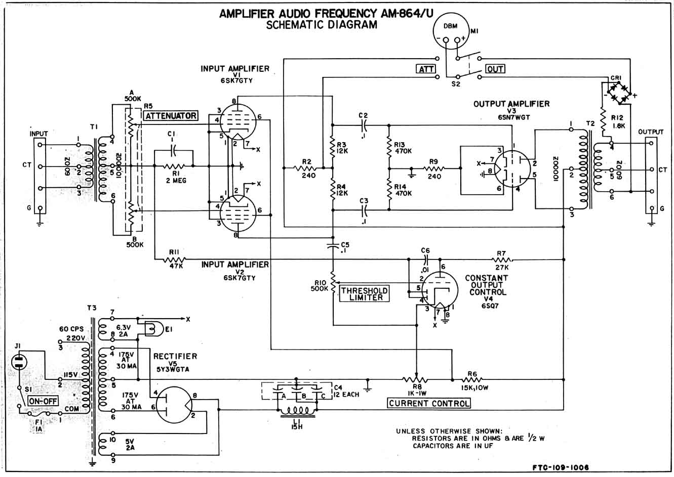
I'm finishing an Federal am864. I had question about the heaters wiring. I didn't wire them the way it is one the schematic, i found it to be a little on the weird side. I did it the classical way, using a center tapped coil. So i tightly twist a pair of wire. One will take the 2 6sk7's pin 2s, the 6sn7's and 6sq7's pins 7. The other one take the 2 6sk7's pins 7 and 6sn7  and 6sq7's pins 8.  What if, for exemple i reverse one? In my understanding, it will change nothing since they are in series, no matter which way we connect it. Why, in the original schematic, for exemple 6sk7's pin 7 are connected to the fillament and pins 2 to gnd, and 6sq7 /6sn7 pins 7 are filament and pins 8 are gnd? Why not 6sk7's pins 2 to filament and pins 7 to gnd? Idoes it eeally matter?

AM-864_Schem.jpg
 
Deepdark said:
Why not connecting it the usual way, just like lot of folks did? For exemple, preservative sounds guy!

The problem with that is that heater current flows through the chassis along with signal current - basically  recipe for hum. Better to keep both legs of the heater separate from the signal 0V and connect them together only at the power supply. Using a CT heater winding is even better as the heater wiring is balanced ad reduces the chance of hum pick up even more.

Cheers

Ian
 
Hello,

you mean two indentical resistors to ground? This is in this case impossible because one side of the heather winding is grounded.

Andreas
 
ruffrecords said:
....that heater current flows through the chassis along with signal current - basically  recipe for hum.
Hello Ian,

it depends on the signal level; perhaps less in symmetrical circuits.

Regards Andreas
 
We mean no heaters to ground. Both heaters legs are connected with a proper wire and heaters meet the vround at only one place, center tap of the filament coil. As Ian said, if we strap one leg to ground, heater current will flow all along the chassis, which isn't a good idea in term of noise/hum. So wiring heater the classical way with a center tapped coil remain the best practice, isn't it?

Another point, is it really important from which way i connect heaters, I mean, if for exemple, the 6sk7 have a yellow wire to pins 2 and a green wire to pins 7 and then, i decide to reverse it so green is pins 2 and yellow pins 7, does it change anything? From my point of view, it's in series so one way or the other will not change anything.

Oh and looking at the shield pin 1,  just out of curiosity, if we do not connect it, it means we will not have the shielding protection and are more prompt to get some interferance noise, or something else?
 
ruffrecords said:
Deepdark said:
Why not connecting it the usual way, just like lot of folks did? For exemple, preservative sounds guy!

The problem with that is that heater current flows through the chassis along with signal current - basically  recipe for hum. Better to keep both legs of the heater separate from the signal 0V and connect them together only at the power supply. Using a CT heater winding is even better as the heater wiring is balanced ad reduces the chance of hum pick up even more.

Thats exactly why I just decided to wire both legs to hearter filament and use a center taped coil and not wiring heaters as per the schematic
 
Deepdark said:
... meet the ground at only one place, center tap of the filament coil.

this is o.k., but in the schematic I don't see the center tap...

Deepdark said:
.. the shield pin 1,  just out of curiosity, if we do not connect it, it means we will not have the shielding protection

Yes

Andreas
 
AndreasS said:
Deepdark said:
... meet the ground at only one place, center tap of the filament coil.

this is o.k., but in the schematic I don't see the center tap

That why i said i did not followed the Schematic. I made the heater wiring in a classical way instead of what the schematic recall
 
AndreasS said:
Hello,

you mean two indentical resistors to ground? This is in this case impossible because one side of the heather winding is grounded.

Andreas

You need to rewire the heaters so they both go direct to the heater winding and are NOT connected directly to 0V. The only connection to 0V is via the centre tap.

Cheers

ian
 
Back
Top