


sahib
Well-known member
A little gadget for CMRR and SYMMETRY trimming and general characteristic testing ( such as frequency response) of 500 and any other type of module/gear. The jig is mainly designed to facilitate the use of unbalanced test equipment in balanced environment. In its basic form it converts unbalanced input of a meter and output of a signal generator to balanced. It also has a simple PHASE switch for checking signal polarity.
The jig consist of a Module Extender and CMRR/SYMMETRY Trimming Card. The module extender has on board test points and allows direct access to all pins of the card edge connector/module using probes.
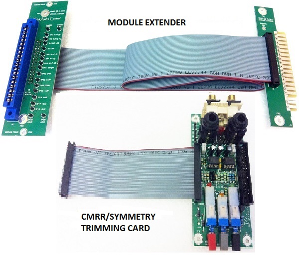
The CMRR/SYMMETRY Trimming Card is inserted between the edge connector and finger cards to facilitate the trimming procedures.
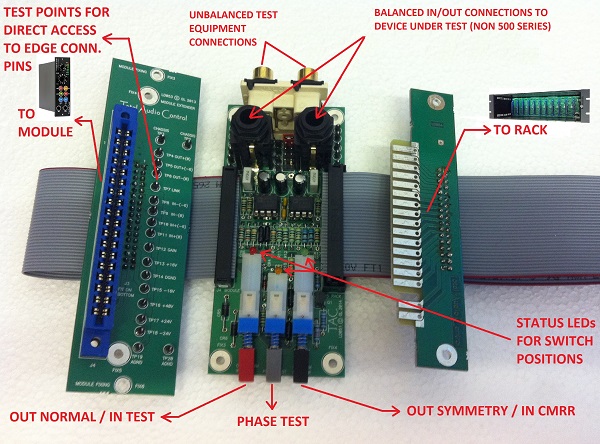
The jig also allows the testing of non 500 standard equipment through the vertically positioned TRS jacks by means of a balanced signal generator output and balanced measuring meter input.
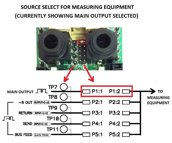
As well as the main output the signal source for the measuring equipment (meter) can also be directed to unbalanced (edge connector) pins such as 3, 7 and 9 by selecting their respective jumpers. Below picture shows the main output selected.
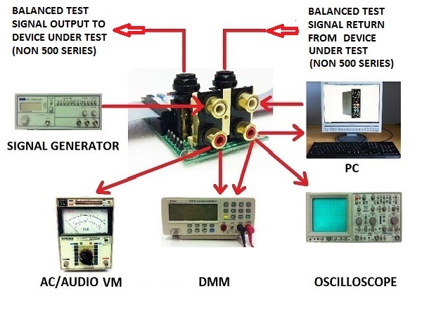
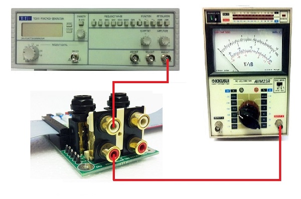
Typical test set up using a signal generator and an AC/Audio Voltmeter.
A scope is connected to the parallel meter output as the second meter.
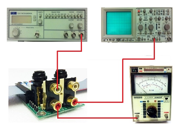
The parallel signal generator output is fed to the second channel of the scope to monitor the test signal. This can also be fed to the second channel of the audio voltmeter.

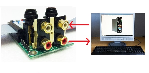
If a computer is to be used it is recommended to use software from True Audio or similar.
http://www.trueaudio.com/rta_abt1.htm - the free version is sufficient to carry out the tests.
User and assembly manual with a good amount of info on CMRR and SYMMETRY. Jig schematic is also included.
http://www.robotica.co.uk/tac/CMRR_TRIMMING_JIG_MANUAL_V3.pdf
And it is available through the White Market http://groupdiy.com/index.php?topic=52462.0
The jig consist of a Module Extender and CMRR/SYMMETRY Trimming Card. The module extender has on board test points and allows direct access to all pins of the card edge connector/module using probes.
The CMRR/SYMMETRY Trimming Card is inserted between the edge connector and finger cards to facilitate the trimming procedures.
The jig also allows the testing of non 500 standard equipment through the vertically positioned TRS jacks by means of a balanced signal generator output and balanced measuring meter input.
As well as the main output the signal source for the measuring equipment (meter) can also be directed to unbalanced (edge connector) pins such as 3, 7 and 9 by selecting their respective jumpers. Below picture shows the main output selected.
Typical test set up using a signal generator and an AC/Audio Voltmeter.
A scope is connected to the parallel meter output as the second meter.
The parallel signal generator output is fed to the second channel of the scope to monitor the test signal. This can also be fed to the second channel of the audio voltmeter.
If a computer is to be used it is recommended to use software from True Audio or similar.
http://www.trueaudio.com/rta_abt1.htm - the free version is sufficient to carry out the tests.
User and assembly manual with a good amount of info on CMRR and SYMMETRY. Jig schematic is also included.
http://www.robotica.co.uk/tac/CMRR_TRIMMING_JIG_MANUAL_V3.pdf
And it is available through the White Market http://groupdiy.com/index.php?topic=52462.0


