Yet Another Monitor Controller design

GroupDIY Audio Forum

Help Support GroupDIY Audio Forum:

This site may earn a commission from merchant affiliate links, including eBay, Amazon, and others.

Andy Peters

Well-known member
Joined
Oct 30, 2007
Messages
2,031
Location
Sunny Tucson
I've been working on a simple monitor controller design.

It has four stereo line-level inputs.

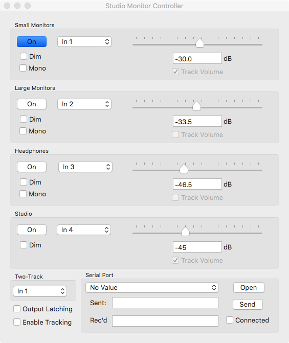
It has five stereo outputs. "small" monitors, "large" monitors, headphones, studio feed, and two-track feed. All but the two-track feed have volume control capability using PGA2320. The monitors and headphone outputs can be switched to mono. Any input can be routed to any output. 

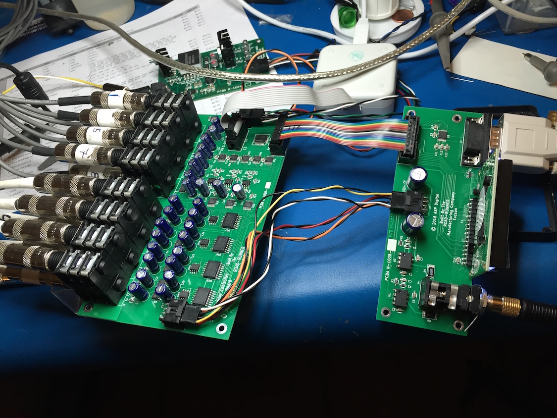
There is a small front-panel board which has the headphone amp and an LCD (for status) display. It has a DE9 jack which speaks standard RS232 to the remote control unit, which is still being designed. It can also connect to a computer's standard RS232 port.

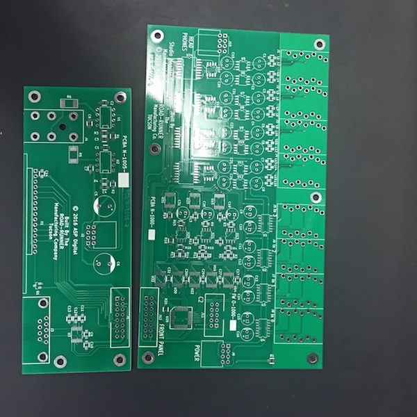
Here are the PCBs. I did the design with Kicad on a Mac. Both boards are two layers, the board on the right has a whole lotta passives on the bottom.

I did the microcontroller programming on the Mac, too, with Silicon Labs' Simplicity Studio IDE (which has the Keil compiler under the hood).

MC_pcbs.JPG
 
burglar said:
Are you making these available?

I've thought about it. Assembled units won't be cheap because the parts aren't cheap and there are a lot of SMT parts to install.

As for offering boards and/or kits, I'm sure that as soon as people see the TSSOPs on the board they'll run screaming.
 
Nice board!

How will the firmware be transfered to the microcontroller? Will this require a JTAG adapter or is there any other way like a USB bootloader?

Cheers,
Carsten
 
culteousness1 said:
Nice board!

How will the firmware be transfered to the microcontroller? Will this require a JTAG adapter or is there any other way like a USB bootloader?

I use the $39 Silicon Labs JTAG pod. I have a serial bootloader design for the C8051F120 that I suppose I could port to the C314, but really, the JTAG pod is so cheap. I looked into using one of SiLabs' newer EFM8 parts which actually have a bootloader but the C314 has the peripherals I wanted.
 
culteousness1 said:
I agree that $39 for a JTAG adapter aren't much. But maybe this is too expensive for others for flashing the firmware once.

This design is an itch that I scratched. Whether someone else could program the micro was not on my list of concerns.

-a
 
Because the hardware-based user interface (knob, buttons) isn't built yet, I wrote a quick little program for the Mac to control the hardware over a serial port. It works with any USB-to-RS-232 dongle for which a Mac OS X driver exists (Prolific, SiLabs, whatever).

The great thing about a software control panel is that it's easily changed!

smc-cp.png
 
looks cool, great work.

(you all knew it would come, so here it is) but: why don't you have a master volume (calibrated in dB SPL) and individual channel trims implemented in your software front end? wouldn't it make sense to (as accurately as possible, lets have this conversation on another occasion) make the different speakers play at the same volume when changing between them. we all know that differences as small as 1/4dB in speaker level will significantly influence the preference for a speaker in A/B listening. of course you can't  or don't necessarily want to match the near field and main speakers, but at least you can try...
this would also be much more convenient in the case of switching, as you do not have to change level or track level changes before switching over.

ok, rant over - great to see you actually working on some gear and to see how professional it looks, scary. sure you are DIY this stuff?

Michael
 
audiomixer said:
looks cool, great work.

(you all knew it would come, so here it is) but: why don't you have a master volume (calibrated in dB SPL) and individual channel trims implemented in your software front end? wouldn't it make sense to (as accurately as possible, lets have this conversation on another occasion) make the different speakers play at the same volume when changing between them. we all know that differences as small as 1/4dB in speaker level will significantly influence the preference for a speaker in A/B listening. of course you can't  or don't necessarily want to match the near field and main speakers, but at least you can try...
this would also be much more convenient in the case of switching, as you do not have to change level or track level changes before switching over.

All of that is eminently reasonable! These are ideas I had not considered.

The interface to the controller hardware is standard RS-232 and the micro on the board interprets simple commands and sets the controls. I had briefly thought about using a CAT-5 cable, like the Dangerous Monitor thing, to tether the controller to a remote user interface board (providing power and communication over the cable) but I figured putting a serial port on it would allow me to control the unit from the computer. This makes debug easier, and also I haven't quite figured out what I want on that user interface remote yet!

Since the communication is RS-232 UART, I can talk to the hardware over a serial port on any computer using a terminal emulator.  The micro on the board receives simple commands and sets the hardware in response.

This little program is my "engineering" control panel, which gives me buttons and sliders as a user interface instead of having to type commands into a terminal. A button press that switches from the small monitors to the large monitors results in more than one command going to the hardware. It sets the level of the small monitors to 0, then sets the level of the large monitors to the desired value, minding the "dim" setting.


To implement your suggestion of ensuring that the levels of both monitors are the same as the user switches between them, it's a simple matter to add an "offset" control to the software to account for possible differences in monitor sensitivity, and then enforce tracking, so when the level of the currently-selected monitors changes, the level of the other changes too.

That said, what I would do if I was setting up a control room would be to use a measurement program like Smaart to help me match the sensitivities of all of the monitors. The adjustment is done using the amp's (or powered speaker's) level control. This way the monitor controller hardware or software doesn't need to manage a sensitivity offset.

ok, rant over - great to see you actually working on some gear and to see how professional it looks, scary. sure you are DIY this stuff?

OK, you got me. I'm a ringer. I design (non-audio) electronics for a living. Most of the work is FPGAs with some microcontroller stuff. The products are very interesting.

But I'm also a live sound mix guy who's done the whole van tour thing and back in the day I had a nice house gig at a club that no longer exists. I'm mostly retired from live mixing but I still fly back east to work with old friends.
 
Here are the stuffed boards:
smc-testing.JPG


The board is only two layers. The top layer has all of the ICs and some of the passives. There is are quite a few passives on the bottom.  It took an evening of soldering to assemble the board. I didn't use hot air, just a Metcal SP-200 with different tips depending on what I was soldering. I used Kester lead-free solder with no-clean flux.

I did the schematic and layout on the Mac using the 4.0.2 stable version of Kicad.

Inputs are on the upper half of the big board, with INA2137 receivers. (THAT1286 will work, too, I just had a tube of the 2137.)

The QFP between the two IDC ribbon-cable connectors is the SiLabs C8051F314 micro.

The row of five TSSOPs  below the micro are ADG5209 dual 4:1 muxes. They were chosen because of their very low crosstalk and distortion specs.

The three SOICs below the muxes are OPA1652 dual op-amps which implement the mono summing for three of the outputs. Each op-amps is followed by an ADG5213 quad switch, again chosen for very low crosstalk and distortion. The switches select the mono sum or the individual left and right lines.

The switch outputs are buffered by more OPA1652s (the column to the right of the electrolytics in the middle of the board) which then drive the PGA2320 inputs. The PGA2320 really needs to be driven from a low-impedance source, hence the buffers.

PGA2320 outputs (which are internally buffered) drive THAT1646 drivers, which are hidden between the two columns of electrolytic caps. The caps are the 10 uF non-polar guys THAT wants.

The switch and mux control lines are routed from the micro around to the right of the board.  The mono select lines go from the right up to each chip. The audio lines that cross these selects are at right angles.

The SPI controls from the micro to the PGA2320 are also routed along the right of the board and they never cross the audio lines at all.

The smaller board to the right is the front panel. It has the MAX3221 RS-232 transceiver (happy with 3.3 V logic-level inputs and outputs), an LCD, and the headphone amp. The multicolor ribbon cable carries the UART and LCD signals as well as +3.3 V for the LCD and +5 V for the MAX3221. The +5 V also goes on the DE-9 jack's pins which are the RS-232 DCD and DSR signals. Those are outputs from a DCE device. The GND and RI RS-232 signals are grounded. When connected to an RS-232 port, those signals are ignored. But they will provide power to the as-yet-unbuild hardware user interface unit.

Also on the front panel is the headphone amp, based on the OPA551 high-current output op-amps. The power and signal for the headphone amp comes over the cable assembly. On this board, the headphone power and ground are entirely separate from the digital power and ground.

The power supply is the small board near the top, with the heat-sinked regulators. It has a 9V DC input. ±15 V comes from the LT1371 switcher (TO-220 heat sink on the left), which outputs ± 18 V after the transformer. That's regulated down to ±15 V by LM317 and LM337 regulators.  I can pull about 500 mA from each rail before the output starts to drop.

The power supply also has a TPS54329 step-down switcher to generate +5 V, and the +5 V is further regulated down to +3.3 V with an MIC37100 LDO.  I can pull an amp from the combined supplies before they complain.

The monitor controller design pulls about 750 mA from the 9 V input. I cannot see or hear any switcher artifacts in the audio. Of course, if one wants, the switching supply can be replaced with a mains transformer, rectifiers and regulators.
 
Andy Peters said:
That said, what I would do if I was setting up a control room would be to use a measurement program like Smaart to help me match the sensitivities of all of the monitors. The adjustment is done using the amp's (or powered speaker's) level control. This way the monitor controller hardware or software doesn't need to manage a sensitivity offset.

well doing this precisely with a pot is difficult, most speakers have jerky little adjustment pots and you can't ever go back to the same value on the speakers after having used them in an other setup.  so you got to go through the same routine again. man, you gotz digital values you can write down and you can leave the pot in a full / detent position....
doing the calibration and having to pull the speakers from their position to access that little pot is a pain too...  just my thinking after having done this quite a few times.  ;)

Michael
 
I think the thing to avoid is any situation that might allow any set of monitors to be driven at maximum level with the amps at maximum gain. You don't want that

Reducing the input gain of active speakers or having fixed attenuators would go some way to preventing that

Nick Froome
 
audiomixer said:
Andy Peters said:
That said, what I would do if I was setting up a control room would be to use a measurement program like Smaart to help me match the sensitivities of all of the monitors. The adjustment is done using the amp's (or powered speaker's) level control. This way the monitor controller hardware or software doesn't need to manage a sensitivity offset.

well doing this precisely with a pot is difficult, most speakers have jerky little adjustment pots and you can't ever go back to the same value on the speakers after having used them in an other setup.  so you got to go through the same routine again. man, you gotz digital values you can write down and you can leave the pot in a full / detent position....
doing the calibration and having to pull the speakers from their position to access that little pot is a pain too...  just my thinking after having done this quite a few times.  ;)

In the live-sound world (where I come from), where the system is set up and torn down for each gig, it is common to leave the amps up full and control levels for each passband from the system processor or crossover. This makes for one less variable to screw up.

But for system installs where the amps are away in a rack away from fiddly fingers, setting the input attenuators correctly, instead of wide full open, is actually standard practice.

In studios, at least those I've been in, the monitors are calibrated to some given SPL for a given input level (and, as Nick Froome points out, to prevent driver destruction), and that is done by adjusting amp input attenuators or twiddling the trimpot on the back of active speakers. And that's done (usually) once. But, yeah, if the monitors are moved and have to be readjusted, it probably makes more sense for their level controls to be at some known, repeatable setting, and calibrate the working levels in the monitor controller.

Nothing in my design precludes either way of working.

 
I forgot to say that the project looks amazing. I am in awe of the abilities of some of the contributors here

Nick Froome
 
Back
Top