Positive lock machining - ideas welcome

GroupDIY Audio Forum

Help Support GroupDIY Audio Forum:

This site may earn a commission from merchant affiliate links, including eBay, Amazon, and others.

Dumbascii

Active member
Joined
Apr 18, 2016
Messages
34
Location
Hancock, MA US
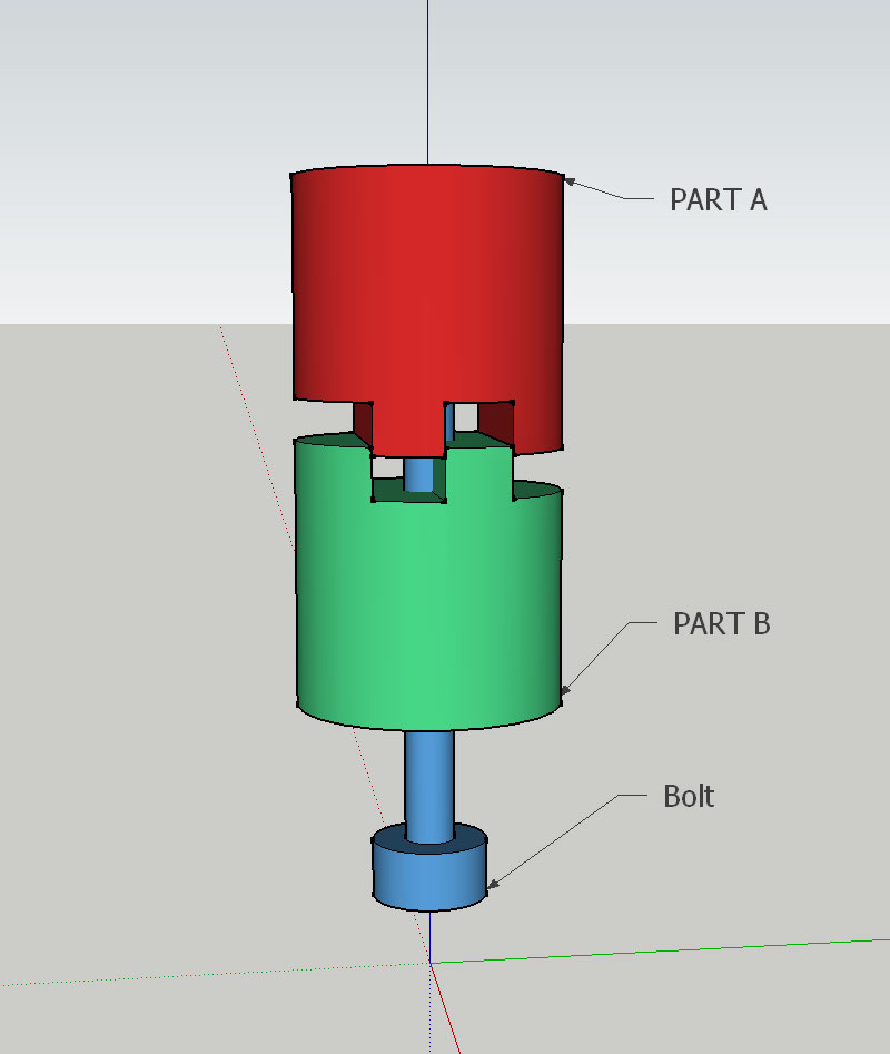
Can you imagine a simpler way to do this? I can imagine a couple of other ways, but they are many machining steps such as pinning or keying. Seems that I'm missing the obvious answer.

Imagine that PART A is a 5/8"-27 threaded stub as would screw into a microphone clip. PART B is say the end of a steel bar. When A & B are attached together with the Bolt, A & B absolutely must not rotate even if the bolt is only finger tight. Plain friction isn't good enough, like if the cylinder faces were flat and the Bolt was tight.
positive-lock.jpg


Thanks!
 
Drilling is always faster and easier than machining. For the easiest way I'd press in a pin on one side and make a hole on corresponding. The 5C collet holders are cheap and greatly facilitate repeatability and setup. Spot drill is a must. Also, depends on what machinery you have available.

Best, M
 
Dumbascii said:
Can you imagine a simpler way to do this?
Sure, if you don't mind ugly.

Clamp in desired position, tack weld, count to ten to cool, bend to break apart. Reclamp, tack weld the other side, count to ten to cool, break apart. Now it only fits together well one way, and won't turn against the fractured mating weld surfaces. Done in two minutes, but you will want to mark some arrows to aid in assembly.

Another two minutes of grinding to pretty it up, still ugly, but functional, and meets your spec as quoted. You did say "simple".

Marik's pin plan above, is probably the real way to do it, I would go with two pins on opposite sides, as it removes the center bolt hole slop from the mating inaccuracy.

Without real machine-shop gear available, just drill two snug slip-fit holes in one shaft face roughly across from each other, insert pins, make larger holes in the other face, enlarge as necessary until it will go together. Fill larger holes with epoxy, assemble with pins mushed into the epoxy, and wait until tomorrow, when the pins are set solid. This removes the requirement of accurate machining.

If one side is not that thick, clamp with the center bolt tight, and drill right through onepiece  into the other, so the holes are aligned.

Are you making just the one, or more than one that need to interchange? If more than one, the epoxy thing will still work, but with epoxy on both sides, using a master to make copies.


Or would this work?

http://www.amazon.com/dp/B0007SL86A/ref=pd_lpo_sbs_dp_ss_1?pf_rd_p=19446876

Gene


you can at least reduce complexity and just mill a groove in the middle on one part and the corresponding cut outs on the other. same number of readjusting the setup, 1/4 less milling. symmetry is probably easier to obtain if you work around the centre axis.

as an alternative:Is a forming operation is out of question? I was thinking of a fan shaped zig-zag towards the center and the counter part. a shallow profile will be sufficient. locks in smaller intervalls, or do you need the one in 360 degrees? how many do you need - cast the part?

- Michael
 
Looks like a skinny roll pin will be the thing. With the bolt tight,  drill from the top face of A straight down into the top face of B. Hammer in a pin.

I have a knee mill and a 9" lathe available and all the fixings. PART A will be steel for making nice threads and B will be aluminum (and larger diameter) for light weight. The reason for separating the A&B parts is to make long 5/8-27 bars that will be cut up into many stubs. It's too hard to thread short stubs with shoulders without breaking tools (again and again!).

A dozen assemblies to start and many more if the project is successful.  :)  The project is a mid-side / Blumlein / you-name-it bar for extremely heavy mics. No plastic, no friction fasteners.

I like the broken weld idea. ;)

I also like the single mill pass idea. The locking shapes only need to be 1/16 deep. Can be simply opposing halves. Can mill several in a row . . .
 
Your drawing looks like a "dog clutch", a crude power transfer coupling.

Depending on how much torque you need to handle, and how much slop it must tolerate, a simpler shallow mating pattern could work.

JR
 
JohnRoberts said:
Your drawing looks like a "dog clutch", a crude power transfer coupling.

I needed to know that term - thanks! It's also like a spline coupler, CV joint... 

This thing also appears to be a dog clutch that I never had a name for: https://on-stage.com/products/view/6114/117191 which On Stage Stands calls a "Posi-Lock Clutch" (it is very useful BTW). As much as I'd like to roll my own, it's highly impractical when these things are under $20.
 
Dumbascii said:
JohnRoberts said:
Your drawing looks like a "dog clutch", a crude power transfer coupling.

I needed to know that term - thanks! It's also like a spline coupler, CV joint... 
A spline coupling and CV joint, are more likely found on a car's driveshaft.
This thing also appears to be a dog clutch that I never had a name for: https://on-stage.com/products/view/6114/117191 which On Stage Stands calls a "Posi-Lock Clutch" (it is very useful BTW). As much as I'd like to roll my own, it's highly impractical when these things are under $20.
Yup commonly used for drum mounts to facilitate multiple angles of engagement.

JR
 
Dumbascii said:
Looks like a skinny roll pin will be the thing. With the bolt tight,  drill from the top face of A straight down into the top face of B. Hammer in a pin.

To drill through seems quite inefficient--all you need is some 3/16" deep hole, rather than going through entire piece and chewing up the tool. Also, using 5C collets is by far faster than tightening the bolt. For steel you'd want to use mist (flood cooling with open knee mill will be way messy) and peck by some .010" to break the chips and cool down the tool. Using a spot first and then Cobalt stubby you'd make lotsa parts without changing the drill. If no mist, use oiling frequently along with pecking.

Set 5C collet, set the distance and then lock 'X' and 'Y', and then drill all the A parts, then change the collet for the B size and with the 'X' and 'Y' still locked drill it. If you use spot drill and Zaxis stopper (available on any knee mill) all the holes will be perfectly aligned and drilled to the right depth.

Use Aluminum part for pressing, and steel for guide holes. You don't need hammering for pressing. If available, use hand press, or a vise--either should work nicely. Just use a small amount of 609 (or similar) Locktite to set it in.

With CNC you could just interpolate the soft jaws and put quite a few parts in a row. With manual you are limited, but still should be quite fast and accurate. 

Best, M
 
Thanks @Marik!  You're right - it *is* excessive.

For now I've moved back to a design where parts A & B are all one piece, threading on the lathe, trying not to crash into the shoulders.  In reality it's a 2" long 7/8 rod with the first 5/8 of length turned down and threaded for 5/8-27 for microphone clips. Aluminum is what I *want* to use but we know how aluminum fine threads gunk and bind. I have some 7075 which is really good about not sticking to tools and fine threaded parts. I'll see how the 7075 threads do after hard anodize. Might be good! Or an expensive failure.  ;)  The point of this thread was to make the threaded area from steel and the rest aluminum.

FYI The lathe and mill are manual. A 50's South Bend and somewhat newer Bridgeport. No DRO. No servos. Fewer operations is a good thing  :D 
 
That manual lathe and mill are very good and can be very accurate even if you go by dials. We have Clausing knee mill and Hardinge lathe manuals--I did not bother putting DRO on either one. Even by dials they are within some .001".

The main thing it is not much fun cutting threads on manual, esp. with a good finish (and you will NEED to use dial indicator). Another way of doing it would be boring the Aluminum and then pressing in an insert like this:

http://www.sweetwater.com/store/detail/AD5B?adpos=1o1&creative=55673940721&device=c&matchtype=&network=g&gclid=COaA0LnK9swCFZRlfgodauAKlg

Of course, with CNC it is cheaper to just cut the thread, but I think for what you do that would be the way to go--then you can make entire thing in one piece out of Aluminum and keep operations to minimum.

Those South Bend lathes are good, but not very rigid, so you will need to take much lighter cuts on steel--probably not more than some 0.010" at a pass (our Mori Seiki easily goes into 304 Stainless with some .060" per cut and .100" in steel). For Aluminum you could do some .040". Leave for finish cut some .003"-.005". The flood would be messy on those machines, but for a good finish use mister and good sharp tools. If no mister available, at least constantly blow with compressed air to keep particles off.

If you need those in larger quantities please contact me--we make those out of SS all day long and equipped with CNC.

Best, Mark

Dumbascii said:
Thanks @Marik!  You're right - it *is* excessive.

For now I've moved back to a design where parts A & B are all one piece, threading on the lathe, trying not to crash into the shoulders.  In reality it's a 2" long 7/8 rod with the first 5/8 of length turned down and threaded for 5/8-27 for microphone clips. Aluminum is what I *want* to use but we know how aluminum fine threads gunk and bind. I have some 7075 which is really good about not sticking to tools and fine threaded parts. I'll see how the 7075 threads do after hard anodize. Might be good! Or an expensive failure.  ;)  The point of this thread was to make the threaded area from steel and the rest aluminum.

FYI The lathe and mill are manual. A 50's South Bend and somewhat newer Bridgeport. No DRO. No servos. Fewer operations is a good thing  :D
 
For whatever strange reason I'm better at cutting internal threads 5/8-27 . I found a tough hooked and pointed boring tool still possessing a tiny bit of carbide in the right direction for internal threading. Of course the awesome fancy razor sharp $30 internal hss thread cutting tool I bought was in pieces almost immediately. :0

Thanks for the lubrication advice. If this thing turns out to be popular I'll give you a buzz. CNC threads are amazing. I'll probably stick to steel for a parkerized finish. Just bore out excess weight.

Wish I could show you the drawings but it might get patented. Ahhhh delusion is bliss...
 
Brass is tougher than aluminum, and easier to cut threads than steel. Looks nice and pretty, too. Although it does squeal like a pig if your tip holder isn't rock-solid, and even sometimes even if it is.

Just sayin'.

Gene
 
I love working with brass but it's 2 to 5 X more expensive. Which is to say 2 to 5 X more expensive scrap when I finish with it.  :p  Some nice patina options though.
 
What's wrong with Al for the threaded piece for finger tightening a 5/8 bolt? I can't imagine when it will wear out.

For the locking system, I think I'd put both pieces together, make a hole between them but mostly on one side, stick a rod on the hole, which should stay in the piece with most of the hole. If the pice is barely tight it will stay there, when you loosen it it will go out or in the notch quite easily. If you start with 2 Al pieces should be quite straight forward to do the hole. At least worth the try I guess.

JS
 

Latest posts

Back
Top