negative compression / past inf. ratio is killing me (VCA / VECA)

GroupDIY Audio Forum

Help Support GroupDIY Audio Forum:

This site may earn a commission from merchant affiliate links, including eBay, Amazon, and others.

tata

Well-known member
Joined
Sep 1, 2013
Messages
171
Location
Hungary
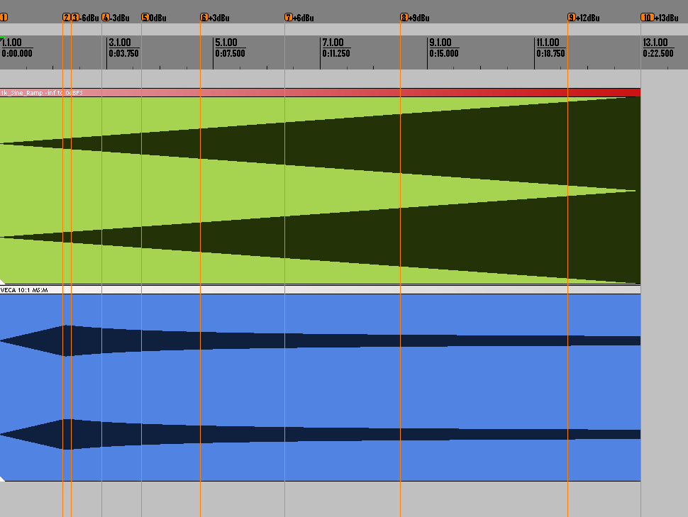
after a few months of troubleshooting i still cant figure out why my VECAs  doing negative compression. its noticeable at 10:1 (and 4:1 too) the most.

i changed the resistors that Gustav noted in his Errata (33k to 16.5k), changed the 1k CV resistors (900R - 1k24) , changed the 120k SC resistor.. still no good.

if i change the 120k to 200k the problem goes away, but the whole unit works/grabs differently.

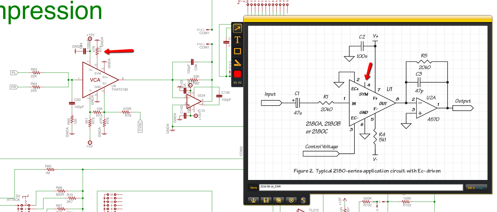
i use 2180B (x3) for the VCAs and THAT1646 / 1206 for the i/o.

any other ideas what i should check, please? (besides the solder joints, cable contacts and the proper components at their places)

many thanks


TwentyTrees said:
  • 1.5:1 gives an increase of 6.3dB on 10dB input increase, therefore 1.56:1
  • 2:1 gives an increase of 5 dB, so 2:1
  • 4:1 gives an increase of 2.5 dB, so 4:1
  • 10:1 gives an increase of 1 dB, so 10:1

Gustav said:
My measurements.

3Khz sine fed from a tone generator.

Comp set in 2:1 (The proposed mod does not affect the internal relation between ratios, so just this ratio is enough for the test)

Setting a reference

-2 dBu to unit, threshold fully out. Adjust make-up gain to match output to -2dBu

Dial in threshold, so output reads -4dBu.

We will now test the assumption that our threshold is set at -6 (4 less than our -2dBu input), which corresponds to a -4dBu (2 less) output at a 2:1 (4:2) ratio.

Test 1.

Adjust test tone to 0dBu.

Output measured at - 3.1dBu.

- 6 relative to the 0dBu input (-6), and a -3.1dBu (0-3 = -3) output 6:3 = 2:1

This holds up to the reference setting with a .1dBu discrepancy.

Test 2.

Adjust test tone to -4dBu

Output reads -4.9dBu.

- 6 relative to the -4dBU input (-2), and a -4.9dBU relative to the -4dBu (-1)  is 2:1

This holds up to the reference setting with a .1dBu discrepancy.

Conclusion

The 0.1dBu discrepancy is so low, it can easily be ignored (maybe just due to the meter).

Ratio functions effectively at 2:1 with no modification to resistor values at normal operating levels.


So what is happening in Tata's test?


As the test under normal operating levels shows, more or less input will generate more or less output, relative to the ratio setting, when signal is above threshold. Test also shows the ratio to be correct in the stock build.

Looking at Tat's test again, it could be the bump at first is the nose of the sine peeking in, slams the signal down, then shows negative ratio type behaviour due to crapping out completely.

It could  be an error in the build, but the resistor change should not be necessary, as my findings show. The ratio is linked to the threshold in this build, and changing  the resistor to a value as high as suggested probably had the side effect of moving the threshold out of the way.

Making up a random tests can be like kicking tires just to see what happens, but for actual trouble shooting, and making comments on a design, it is advisable to measure the voltage of the signal and follow a more scientifically minded approach

Starting with a controlled test would be preferable to rule out any build error or "made-up" problems.

Sending a rising sine wave, 100% identical to L/R in the compressor at random, can in itself give skewed info, and the interpretation will be nothing more than interpretation.

Hope that helps.

Gustav
 
Gustav,

thank you for your reply.

let me add my own notes to your test, "translating to RME FF800", etc.

my RME settings:
Output level at 0 dBFS @ +4 dBu: +13 dBu  (75 Ohm)
Input level for 0 dBFS @ +4 dBu: +13 dBu  (10k)

so 0dBu = -13dBFS = 0.775V  (AC, pin2-pin3, measured it, it seems to be correct - tho i only have a no-true-RMS multimeter)

now "Setting a reference" :  (attack:fast, release:fast, ratio 2:1, threshold fully open, HPSC off, MS:M, DW mix : off)
im sending signal on L-R channels, so both i/os are connected.

* i set up the tone generator out to 3k sine, -15dB(FS)  (= -2dBu). RME input shows -15dB(FS) too, with VECA Gain fully down
* i turn Threshold (CCW) so RME input meter shows -17dB(FS) (= -4dBu)

"Test 1" :

* i adjust the tone generator out to -13dBFS (=0dBu)
* compressor output (RME input) measured at : -16.1dB(FS) (=-3.1dBu)
check. (pass)

"Test 2" :

* test tone set to -17dB(FS) (= -4dBu)
* output (RME input) reads : -18dB(FS) (= -5dBu)
check. (pass)

same tests in MS mode set to "S" - nearly the same measurements, +/- 0.1 dB

this is with the "stock" value resistors (120k, 2x 33k, etc) - all original, except the release circuit fix.
so i think i did what you wrote and should be happy, right?

but..

..now please do this on your VECA:  (still both channels having the same sine input)

* 1k sine input at 0dBu (= -13dBFS out on my RME) , 10:1 ratio, MS : M, Threshold fully open, Gain : min. (others as above)
  VECA output is -13dBFS (0dBu) on my RME meter.
* set Threshold so the VECA out (RME in)  is 10dB less. RME input shows -23dBFS, (-10dBu).
  my VECA meter shows 10dB GR.

* adjust test tone to +3dBu (tone generator to -10dBFS here)
i get -24.6dBFS (-11.6 dBu)

* adjust tone generator to +6dBu (tone generator to -7dBFS here)
i get -26.4dBFS (-23.4 dBu)

* adjust tone generator to +9dBu (tone generator to -4dBFS here)
i get -28.1 dBFS (-15.1dBu)

* adjust tone generator to +12dBu (tone generator to -1dBFS here)
i get -30dBFS (-17dBu)

this is how it looks like on that skewed recording :  (blue item (=VECA output) is compensated by +10dB in post, for better visibility, Marker 2 shows -7dBu)

VECA_neg_10-1_001.png


is this OK?
 
tata said:
is this OK?

A few tips for moving on with it.

If you are measuring singular mono material shot to both channels, I would advice you to test one channel only instead of both at once. For a mono signal fed to both channels, adding 1dB on your DAW fader will be a 1dBU increase of both channels, which then amplifies the center content due to the nature of MS processing, and  further amplifies it on the side chain VCA. The way you are testing dictates that turning up the fader sums your values to the side chain.

Also keep in mind, that even on the S setting, the side chain is still MS, just with more relative amplitude on side content i the side chain - most center bump on the M setting.

The solution is to measure with just one channel, or do the math to adjust for the signal level you are actually adding to the unit. I can't do the math

If this is your "problem", and you insist on changing things to accommodate for it, adding a 10K resistor on the M signal in the side chain where theres currently a 0R resistor may get a result towards a solution to what you are trying to do. In that case, you can nix the resistors in parallel on the earlier opamp stages, if you feel side chain signal is coming in too weak - this is just guessing.

I dont current have a unit on the bench, so I can't offer to replicate your dual-mono approach, so to move forward now, you'd have to use the single channel approach to definitively rule out a build error.

Its not clear if you are thinking the ratio in reverse by your initial setting. I would thread a little lighter than what you are doing.

I do not see how your threshold reference is actually verified with your method. Maybe I am overlooking something, but make sure that you have verified your threshold axis - consider both an up and down measurement for the 1:10 ratio, so you know whats compression, and whats gain on the output. Make-up gain at minimum suggest you have the pot fully CCW, but maybe you mean adjusted to zero gain.

And once again, I would keep levels more conservative.

6dBU level per channel = 12dBU total + 6dB mid bump in MS circuit if set to full M , and a bump on the summing VCA with your dual, mono input = hot, hot, hot.

Measuring at levels comparable to the ones you did on the 1:2 setting on a single input could save your life...

Hope that helps.

Gustav
 
To test the 10:1 ratio.

Send a single channel -5dBu  sine wave to the left input of the unit.
Adjust threshold for an output of -9.5dBu

Testing the assumption that threshold is now set to -10dBu
(difference between -10 and -9.5 is 1/10th of the difference between -10 and -5).

Test 1

Adjust input signal to 0dBu.
Measure output signal (Assumption predicts -9dBu)

Test 2

Adjust input signal to -8dBu.
Measure output signal (Assumption predicts -9.8dBu)

Gustav
 
To test the 4:1 ratio.

Send a single channel -4dBu  sine wave to the left input of the unit.
Adjust threshold for an output of -10dBu

Testing the assumption that threshold is now set to -12dBu (Difference between -12 and -10 is 1/4th of the difference between -12 and -4. 

Test 1

Adjust input signal to 0dBu.
Measure output signal (Assumption predicts -9dBu)

Test 2

Adjust input signal to -8dBu.
Measure output signal (Assumption predicts -11dBu)

Gustav
 
following your test method:

10:1
Test 1 : i get -12.2dBu (-25.2dBFS)
Test 2 : i get - 8.2dBu (-21.2dBFS)

4:1
Test 1 : i get -10.7 dBu (-23.7dBFS)
Test 2 : i get  -9.6 dBu (-22.6dBFS)

single channel input (left only), attack/release: fast, MS:M, HPSC off, Blend off, Gain at minimum

you wrote : "consider both an up and down measurement for the 1:10 ratio.."  - i guess you mean 10:1
"Measuring at levels comparable to the ones you did on the 1:2 setting" - i guess you mean 2:1
"Make-up gain at minimum suggest you have the pot fully CCW, but maybe you mean adjusted to zero gain." - i meant fully CCW.

soo. this is not right. i guess.

could a VECA owner chime in and test these, please?

 
in the meantime..

when you wrote :

" - You can't read a schematic (No, theres no need to lift pin 4, since its not connected)."
can you please comment this?:

VCA_2180_pin4_001.png

 
tata said:
in the meantime..

when you wrote :

" - You can't read a schematic (No, theres no need to lift pin 4, since its not connected)."
can you please comment this?:


I really feel lost when I try to help you. You pointed out the problem with the caps on the release, and I told you instantly, its an error, which will be corrected. Is it not clear to you that I am happy to make corrections when there are errors in my work?

I am trying to help, but you ignore key elements, then revert to pointing out silk screen markings being disturbed by lines, or a typo in picofarad in the assembly guide.  I get a feeling that  the urge to be right about something is what drives you, rather than reaching a steadfast conclusion.

My post that contained the comment about the schematic on an earlier occasion was frustrated and aimed at the discrepancy between attitude and ability. I was at a point where I couldn't take another reference to "rock n roll" levels, rather than doing controlled measurements.  It was frustrating to see you ask if anyone else would replicate your nonsense test, when I had provided you with sufficient info and the instructions to do a meaningful one, and theres no doubt I made that clear.

Following that, I apologised for showing my frustration and made it clear to you, I want to come to a conclusion, and again, I have tried to help.


Gustav said:
tata said:
i dont see why i should not push the gears "hot"

You should do what you want - you seem confident and content in your approach, and I realise now that my last post was misplaced.

tata said:
btw 2180B - no need to disconnect pin4 in this circuit?


- You have to ask how to reverse a bypass switch.
- You think dBFS is an absolute level reference, and keep clinging to the notion theres some validity to your position instead of accepting the info given to you.
- You are "not good enough at math" (by your own account) to follow the test I shared, but you are confident enough in your ability to completely ignore it and my requests for a valid measurement.
- You insist that pushing a sine wave into the unit at completely unknown levels is somehow a meaningful test.
- You think other builders can replicate your test without any reference to levels.
- You do not care (or know how to?) measure, if you are pushing 20dBU into the unit
- The unit should be able to take any level going into it (Rock n Roll)
- You can't read a schematic (No, theres no need to lift pin 4, since its not connected).

I think there is a discrepancy between what you know, which conclusions you have drawn, and what you aim to achieve thats hard to overcome. I am used to helping people who have no basic knowledge. It seems I dont know how to help people who lack basic understanding, but somehow still knows everything.

If you want to get serious about trouble shooting, I would ask you to bring the unit back to stock configuration, manufacture a steady sine wave at around 1-3KHz at a level of 0dBU (0.775V), or maybe even just measure the voltage on your output with aforementioned sine  wave, so we can at least get some idea of your converter levels. That way,  we can possibly rule out flawed testing and start looking for the build error.

If not, just keep going, as long as you are happy with what you get out of it.


Gustav


  • tata said:
    following your test method:

    10:1
    Test 1 : i get -12.2dBu (-25.2dBFS)
    Test 2 : i get - 8.2dBu (-21.2dBFS)

    4:1
    Test 1 : i get -10.7 dBu (-23.7dBFS)
    Test 2 : i get  -9.6 dBu (-22.6dBFS)

    Your data on 2:1 correlated with direction of movement, but these number are indeed nonsense. If you replicated the procedure I wrote, there is an error in your build. [/quote]

    tata said:
    could a VECA owner chime in and test these, please?

    I provided you with data, and this is from the VECA help thread.

    TwentyTrees said:
    • 2:1 gives an increase of 5 dB, so 2:1
    • 4:1 gives an increase of 2.5 dB, so 4:1
    • 10:1 gives an increase of 1 dB, so 10:1

    Maybe someone else will chime in, and I wish you the best in trying to reach a conclusion that suits you at some point - I'll leave you to it.

    tata said:
    you wrote : "consider both an up and down measurement for the 1:10 ratio.."  - i guess you mean 10:1
    "Measuring at levels comparable to the ones you did on the 1:2 setting" - i guess you mean 2:1

    Yes, you are correct - thats exactly what I meant. Thanks for taking the effort to clear that up.

    Gustav
 
so no comments on my new tests that i could really use?
no tips on what i shoud check to fix the negative ratio problem? (is this how a proper VECA is crapping out?)

i thought its easy for you as the designer of VECA to answer to my questions, but it seems its not.

im not doing this to prove me right. i care about having 5 correctly working VECAs.
five.

you insulted me w/ saying "i cant read a schemo" but still didnt answer my tech questions.

this feels hopeless..  :(

 
Gustav said:
I really feel lost when I try to help you. You pointed out the problem with the caps on the release, and I told you instantly, its an error, which will be corrected. Is it not clear to you that I am happy to make corrections when there are errors in my work?

i also pointed out the resistor orders (w/the caps in paralell)
i see no notes in the Errata for that.

i guess you copied from Gyraf, and he also has that wrong, as it turned out.

im still interested in learning how VECA / VCAs work, and whats the reason of the difference between VECA and THAT's schemo
(pin 4, and the surrounding resistors, like R5 (R82 in VECA) and the CVSC)

if there is/are mistakes in my builds, im ready to fix and ready to admit that i messed up.

i couldnt care less about these measurement, IF my ears wouldnt catch the negative compression on a simple vocal buss - at levels we usually work. i just want it work as expected. but its not, atm.

peace.

 
tata said:
i also pointed out the resistor orders (w/the caps in paralell)
i see no notes in the Errata for that.

Thank you so much for bringing that up.

Its a stacked release, its different from the SSL,but still two times stacked, hundreds of people (including me) have used their GssL on the auto-release setting and enjoyed it, and on the VECA, theres even a second stack with different values for auto-release.

So I am sorry if this is irritating, but I will not be adding errata to reverse the order of those two resistors.


Gustav
 
Gustav said:
It was frustrating to see you ask if anyone else would replicate your nonsense test, when I had provided you with sufficient info and the instructions to do a meaningful one, and theres no doubt I made that clear.

id still love to get feedback form a VECA user to replicate my "nonsense" test - a simple ("skewed") test that clearly shows the negative compression at 4:1 and 10:1 in my builds.

you wrote if 2:1 is OK, then the rest are ok too.
but it seems they are not.

its not irritating to me if you dont add that resistor order to your Errata. i modified it to match the original anyways.
 
Gustav said:
If this is your "problem", and you insist on changing things to accommodate for it, adding a 10K resistor on the M signal in the side chain where theres currently a 0R resistor may get a result towards a solution to what you are trying to do. In that case, you can nix the resistors in parallel on the earlier opamp stages, if you feel side chain signal is coming in too weak - this is just guessing.
Gustav

is that R59 in VECA?
VECA_R59.png

if yes, im changing it to 10k right away. easy mod, as i have those 0Rs socketed too.


tata said:
you wrote if 2:1 is OK, then the rest are ok too.
but it seems they are not.

Gustav said:
Comp set in 2:1 (The proposed mod does not affect the internal relation between ratios, so just this ratio is enough for the test)

I am sorry if this was unclear when I posted it, but the context was your suggested mod.

I have done measurements on the other ratios - I also refer a second time to the data posted in the mentioned thread.


And I am sorry, but I thought your call for further data meant you were not looking to do further trouble shooting.

If you want a comment on the data you measured, I can offer the following.

Your 2:1 measurements check out, which is more odd to me than the rest, but to start.

For the 10:1 ratio.

The reference set should correspond to a threshold of -10dBu, input of -5dBu, output of -9.5.  (5 dB above the threshold, divided by 10 = 0,5 for  total of 0,5dB gain above threshold.

Your test 1 measurement (0dBu input)  is -12,2dBu, which negates the test completely. First of all, amplitude is falling, when it should be rising, regardless of ratio or threshold setting, but not only that, at a -10dB threshold, and a 0dB input, whatever the ratio is, it should fall somewhere between -10dB and 0dB.

Your test 2 measurement (-8dBu input) is -8.2dBu, So this is also reversed, amplitude is rising compared to our test point, when it should be falling, and corresponding to an input of +8dBu, if the test conditions were correct.

This is so far off, I wouldn't  know what to suggest.

Gustav
 
tata said:
is that R59 in VECA?
VECA_R59.png

Yes, you are 100% correct.

tata said:
if yes, im changing it to 10k right away. easy mod, as i have those 0Rs socketed too.

Based on the data you came back with, this has no significance in relation to your problem whatsoever. It will merely lower the M content of the M/S blend, and was merely a suggestion/guess before I had the data back from you.

Gustav
 
tata said:
(is this how a proper VECA is crapping out?)

I am sorry if this was unclear, but doing measurements at more conservative, referenced level was a means to rule out the high levels sent to the side chain as a possible error source.

Gustav.
 
tata said:
lift pin 4, since its not connected

Sorry, sometimes feel like you are so many places at once, that things get lost.

This is a symmetry pin, not connected ont he pretrimmed VCAs.

Not related to your problem, and again - ratios have been verified.

Even if theres some special problem on your build, I  do not see how it would affect anything significantly, since its going to ground, not a calibration circuit. On the calibration circuit, it would be trimmed for lowest THD with reference to the negative and positive supply voltages on the 2181. Your chip is pre-trimmed, so lift it off.

Gustav
 
tried the R59 mod (0R to 10k) - didnt solve the main issue.

about the pin4 question : it puzzled me why you having it connected at all, since you have "2180" labeled there.
for 2181 i could understand that connection, but again.. im just following your PCB / schemo values.

i put a 2180 where 2180 is marked.

i hope you get my point.

could it be that my front control PCB has some mistake - i mean the Ratio circuit ?
i will disassemble this unit, take out that PCB and re-re-recheck all components.

can you pls tell what R82 does, and what difference is expected if id change it to 20k (as its shown on the THAT schemo)?
R82 is not socketed in my builds, but im ready to play with it - if it would make significant change.

thanks.
 

Latest posts

Back
Top