Echo North
Well-known member
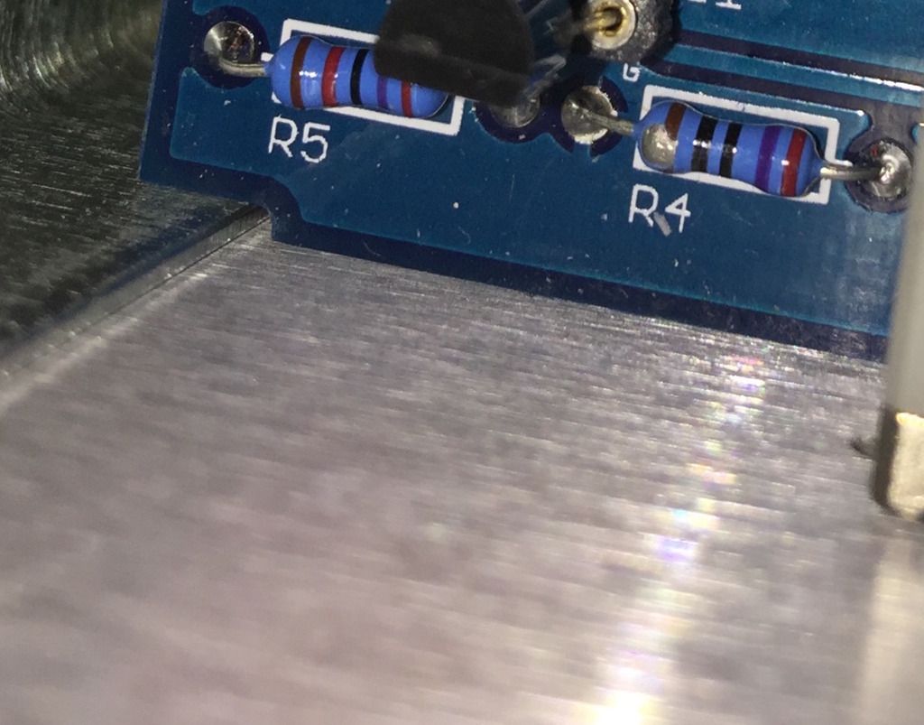
seanweaverguitar said:Many thanks Mike. It tests to other cross-hairs on the top side and I will check it when I put in the new diode. I'm a bit confused, because there are cross-hairs on the bottom of that hole also, so aren't the ground planes connected on both since there are cross-hairs on both sides of that hole? Much appreciation for a great product.
True, looks like the board has a dual plane (I didn't lay it out).