[BUILD] New FET/RACK Official Help Thread - Please read first post!

GroupDIY Audio Forum

Help Support GroupDIY Audio Forum:

This site may earn a commission from merchant affiliate links, including eBay, Amazon, and others.
Nao_Idea said:
TP21

20:1 -6.49 DCV
12:1 -4.377 DCV
8:1    -3.586 DCV
4:1      -2.921 DCV

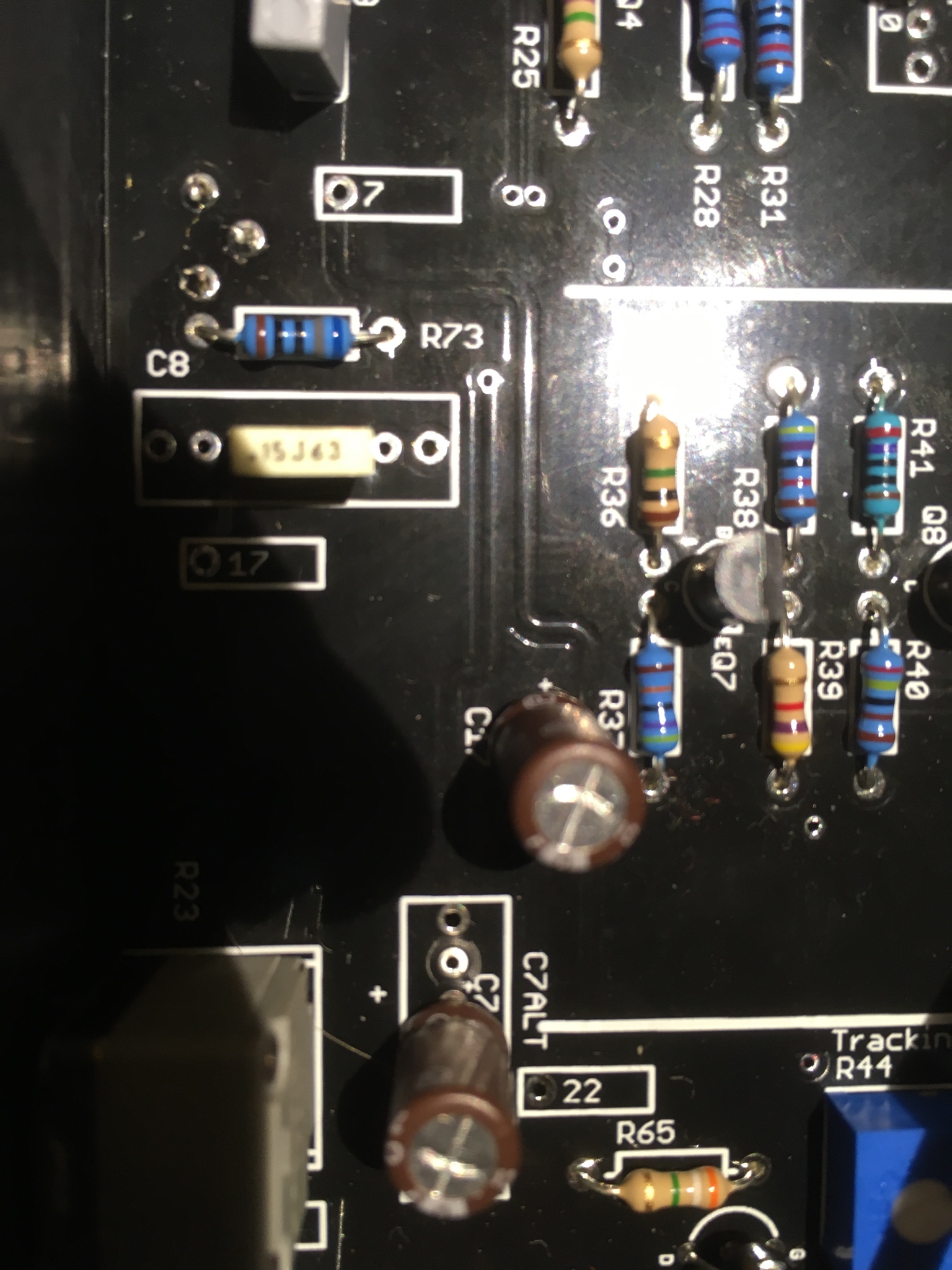
I do not have voltage at the negative of CR3/4.

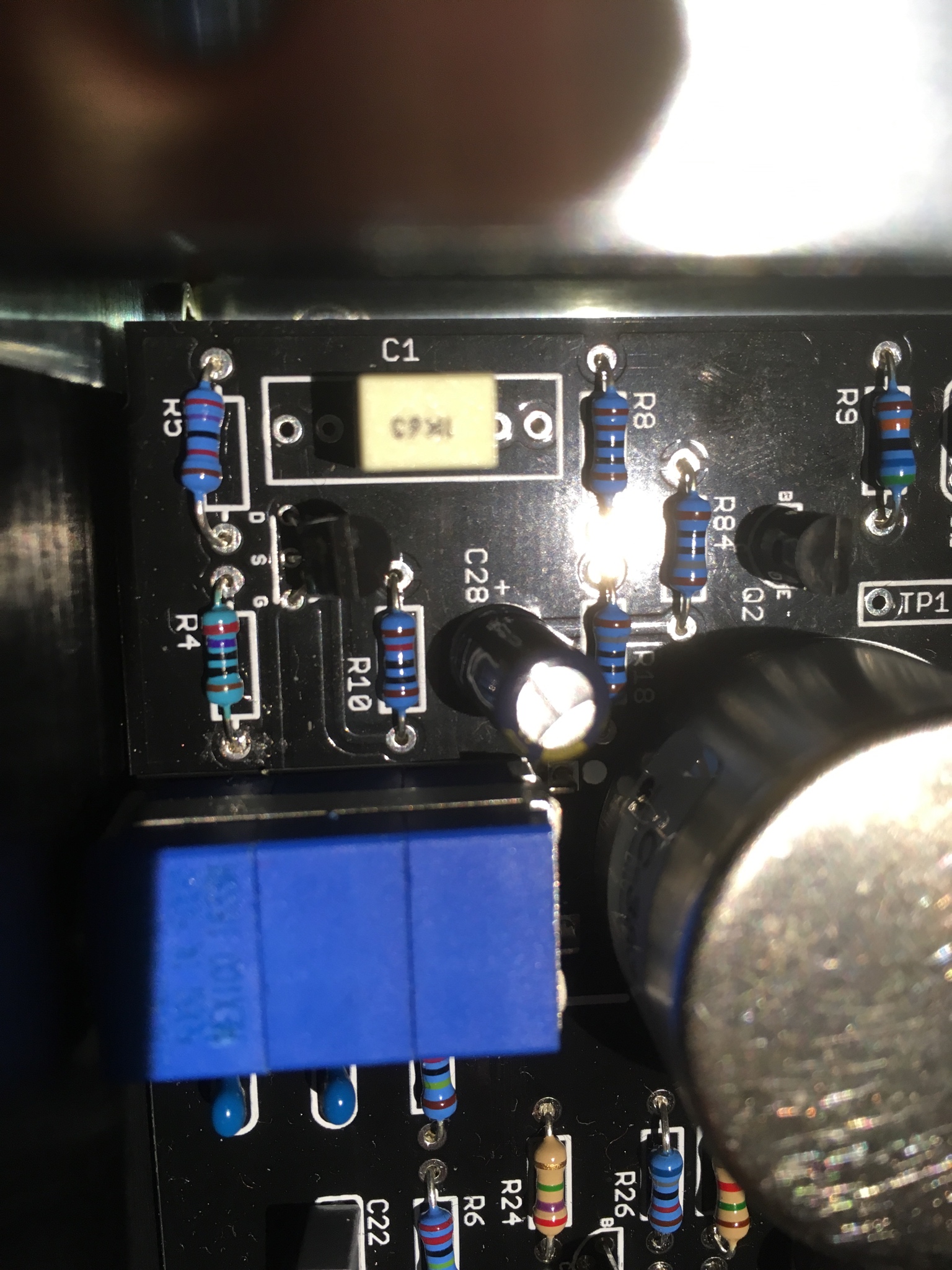
All three legs are attached.  I removed the pot and I think I put too much solder on the joint and it might flowed to the other side and been jumping the pins.  When I re-installed the Release Pot, the drop on the VU meter was significantly less.  Originally the drop was -10 to -20 on the VU meter.  After I removed the release pot and re-installed it, the drop is -0.5 to -1 on the VU meter (it seems to decrease as the unit warms up). 

I measured the resistance of the release potentiometer and I found the following values while it was off of the board. 

Pot Full CCW
Pin 1 to 2:  0.2 Ohm
Pin 1 to 3:  5.46 MOhm
Pin 2 to 3:  5.46 MOhm

Midway
Pin 1 to 2:  2.8 MOhm
Pin 1 to 3:  5.5 MOhm
Pin 2 to 3:  2.8 Mohm

Full CW
Pin 1 to 2:  5.5 MOhm
Pin 1 to 3:  5.5 MOhm
Pin 2 to 3:  0.2 Ohm

Up Date: I left the unit on for a while so it would warm up, I wanted to see how much the meter changed.  The needle was reading a little over +1 on the VU meter.  I zeroed the meter and tried the Release knob to see the change.  It was maybe a needle width.  I can live with this.  It it seems to be normal and functioning properly. 

Thanks again,
Mike

Working now?

A needle worth of swing on the release pot is normal.

Mike
 
Deejsirois said:
I have modified my description. Still the same issue though

So are you getting a 10dB drop on the audio at the output?  Where are your in and out set to get that?

Or is this strictly an issue with the meter?

Mike
 
Hello,

Finished building a rack F tonight - well, sorta... 

I'm not getting any compression apparently?  The unit passes audio with out distortion or hum - both the front input and output controls do as they should, but no matter where the attack or release knobs are set, the meter stays fixed and there's no audible compression going on which means that the meter is reflecting what is going on?  I've doubled checked everything I can think of as well checked all of the solder points.  So, at this point, I'm not sure where to start with trouble shooting?  Any suggestions would be greatly appreciated.

That aside (understanding I cannot fully calibrate without the compression working as stated above), after reading Hairball's Calibration page, I'm confused about how to exactly calibrate this unit?  I finished an A unit a few weeks ago that went well, but I'm getting lost in the F calibration instructions.  Seems to be missing steps and / or referencing adjustment points that are not documented in the instructions, or is it just me? If I'm not mis-reading, anyone know where there might be step-by-step F calibration instructions?

Thanks in advance...
Greg
 
ron_swanson said:
Hello,

Finished building a rack F tonight - well, sorta... 

I'm not getting any compression apparently?  The unit passes audio with out distortion or hum - both the front input and output controls do as they should, but no matter where the attack or release knobs are set, the meter stays fixed and there's no audible compression going on which means that the meter is reflecting what is going on?  I've doubled checked everything I can think of as well checked all of the solder points.  So, at this point, I'm not sure where to start with trouble shooting?  Any suggestions would be greatly appreciated.

That aside (understanding I cannot fully calibrate without the compression working as stated above), after reading Hairball's Calibration page, I'm confused about how to exactly calibrate this unit?  I finished an A unit a few weeks ago that went well, but I'm getting lost in the F calibration instructions.  Seems to be missing steps and / or referencing adjustment points that are not documented in the instructions, or is it just me? If I'm not mis-reading, anyone know where there might be step-by-step F calibration instructions?

Thanks in advance...
Greg

Calibration is the same, you just don't have to do the Null Adjust.

if you're not getting compression, there is something wrong in your side chain. These the the TP 22, 20, 21.  Here is how to test:

https://www.hairballaudio.com/blog/resources/post/fetrack-troubleshooting-guide
 
Hairball Audio said:
Calibration is the same, you just don't have to do the Null Adjust.

if you're not getting compression, there is something wrong in your side chain. These the the TP 22, 20, 21.  Here is how to test:

https://www.hairballaudio.com/blog/resources/post/fetrack-troubleshooting-guide

Thanks for the response!

Before I get into measuring on the bench...

After reading through the troubleshooting guide linked in your response, I don't see the F revision specifically indicated.  A lot of the voltages seem to be fairly similar between the indicated A and D revs, so would it be safe to assume that the F rev would also be in the same ball park?  If so, would the F be closer to the D or ?
 
ron_swanson said:
Thanks for the response!

Before I get into measuring on the bench...

After reading through the troubleshooting guide linked in your response, I don't see the F revision specifically indicated.  A lot of the voltages seem to be fairly similar between the indicated A and D revs, so would it be safe to assume that the F rev would also be in the same ball park?  If so, would the F be closer to the D or ?

Use the D as a reference.

The AMP stages may not be as hot, but general ballpark is good.
 
Hairball Audio said:
Use the D as a reference.

The AMP stages may not be as hot, but general ballpark is good.

I don't seem to have any voltage at Output Trans BRN?

TEST POINT LOW HIGH VOLTAGE
0. Power Supply
CR8 30.80 VDC
CR9 -9.57 VDC

1. QBias Voltage
TP18 0 - 2.74 VDC

2. Amplification Stages
TP1 0.095 VAC
TP15 1.855 VAC
TP17 0.347 VAC
Output Trans BRN 0.00 VAC
Output XLR + - 6.457 VAC

3 -  GR Control Amp Input
TP22
20:1 0.467 VAC
12:1 0.303 VAC
8:1 0.239 VAC
4:1 0.182 VAC

4. - GR Control Amp Output
Anode CR2
20:1 0.890 VAC
12:1 0.999 VAC
8:1 1.192 VAC
4:1 1.621 VAC

5. -  GR Control Amp Threshold Voltages
TP21
20:1 -6.499 VDC
12:1 -4.408 VDC
8:1 -3.620 VDC
4:1 -2.957 VDC

Hopefully I'm not reading the Output Trans BRN voltage incorrectly... meaning, I'm not getting an inaccurate.  I took the unit apart and doubled checked the solder joints, and check that the competes in the signal line amp were correct.  The next step is checking Q5,6,7,8,9 match (closely) the voltages on the schematic?  If so, do I do that with an input applied and with what front panel settings?

 
Sorry on the F it's RED instead of Brown.

CR2 voltages seem backwards...did you mess up that labeling?  20 should be higher than 4:1.  Those voltages also seem a little low.

I'd check the voltages in that GR amp.  Make sure you don't have something like a 4.7K/470R/470K swapped.

Mike
 
Hairball Audio said:
So are you getting a 10dB drop on the audio at the output?  Where are your in and out set to get that?

Or is this strictly an issue with the meter?

Mike

Strictly an issue with the meter
 
Hey guys! I just finished my build of the Rev D and it doesn’t work. Groundish-hum is everything I hear. Will of course look for shorts when I’m back at the studio, but I have a question for now.

I accidentally broke the Resistors with the value 1Kohm and 0,5 watt that’s supposed to be soldered to R81 and R82. All I had to replace them with was two resistors a 1Kohm and 0,25 watt  and I figured it was worth a shot. Could this be the explanation to the hum and no signal that the power supply has not enough voltage? Will I need to change those to 0,5 watt anyway?

The CN15 that connects the power to the VU-meter lamp was missing in my package, so that’s not attached. But I’m guessing this doesn’t explain why the unit is not working?

Thankful for any answers!
Joar
 
Joarsylvan said:
Hey guys! I just finished my build of the Rev D and it doesn’t work. Groundish-hum is everything I hear. Will of course look for shorts when I’m back at the studio, but I have a question for now.

I accidentally broke the Resistors with the value 1Kohm and 0,5 watt that’s supposed to be soldered to R81 and R82. All I had to replace them with was two resistors a 1Kohm and 0,25 watt  and I figured it was worth a shot. Could this be the explanation to the hum and no signal that the power supply has not enough voltage? Will I need to change those to 0,5 watt anyway?

The CN15 that connects the power to the VU-meter lamp was missing in my package, so that’s not attached. But I’m guessing this doesn’t explain why the unit is not working?

Thankful for any answers!
Joar

1K 0.25W resistors would eventually fail.  We'll get those missing parts out to you. Also, make sure all 3 L-Brackets that connect the main PCB to the enclosure are in place, they are part of the grounding.

In the mean time:
https://www.hairballaudio.com/blog/resources/post/fetrack-troubleshooting-guide
 
Thanks! I’ve sent you an email with my order number.

I have a signal now, very low and sort of distorted.

I’ve done the tests 2 and 4 and this is the results:

TEST 2
TO1: .083 VAC
TP 15: 0.00
TP: 17 0.00
Output trafo Brn: .114 VAC

TEST 4
20:1 ratio: 0
12:1 ratio: 0
8:1 ratio: 0
4:1 ratio: 0

All this is done with input metering .775 VAC.

There’s something going on, and sometimes when messing around with the ratio buttons for 10 minutes I get a clean and strong signal (that I don’t think is compressed), and when I touch the attack knob it collapses and goes back to low and distorted.

All resistors and components are in the right places (i’m pretty sure, tripple checked every component and measured it).

Could I maybe send the PCB back to you for a repair or a trouble shoot? Bevausw there’s so many potential wrongs which I dob’t have tha answers to. Haha.
 
Joarsylvan said:
Thanks! I’ve sent you an email with my order number.

I have a signal now, very low and sort of distorted.

I’ve done the tests 2 and 4 and this is the results:

TEST 2
TO1: .083 VAC
TP 15: 0.00
TP: 17 0.00
Output trafo Brn: .114 VAC

TEST 4
20:1 ratio: 0
12:1 ratio: 0
8:1 ratio: 0
4:1 ratio: 0

All this is done with input metering .775 VAC.

There’s something going on, and sometimes when messing around with the ratio buttons for 10 minutes I get a clean and strong signal (that I don’t think is compressed), and when I touch the attack knob it collapses and goes back to low and distorted.

All resistors and components are in the right places (i’m pretty sure, tripple checked every component and measured it).

Could I maybe send the PCB back to you for a repair or a trouble shoot? Bevausw there’s so many potential wrongs which I dob’t have tha answers to. Haha.

Your amp section is dead but it sounds like it can spring back to life.  Thank makes me think you have a bad/loose/unsolder joint. But it could be something else. Your issue is in the section labeled "Signal PreAmp".

Yes we do have a flat rate repair service:
https://www.hairballaudio.com/build-support-services

Mike
 
Hairball Audio said:
Sorry on the F it's RED instead of Brown.

CR2 voltages seem backwards...did you mess up that labeling?  20 should be higher than 4:1.  Those voltages also seem a little low.

I'd check the voltages in that GR amp.  Make sure you don't have something like a 4.7K/470R/470K swapped.

Mike

Hi Mike,

I've gone back and taken pictures of each PCB section and then one-by-one reconfirmed / checked each and every resistor visually and some physically (removed from circuit).    All seems as it should be. 

I then went back and re-measured all this time using the RED transformer lead instead of the BRN as originally tested.    I got a reading this time, but still low compared to the rev D numbers.  For whatever reasons, this time around the compression ratios read pretty uniform no matter what ratio is selected.  Now, I'm even more confused and things look worse...


TEST POINT LOW HIGH VOLTAGE
0. Power Supply
CR8 30.80 VDC
CR9 -9.57 VDC

1. QBias Voltage
TP18 0 2.747 VDC

2. Amplification Stages
TP1 0.099 VAC
TP15 1.958 VAC
TP17 0.389 VAC
Output Trans RED 1.905 VAC
Output XLR + - 7.26 VAC

3 -  GR Control Amp Input
TP22
20:1 0.418 VAC
12:1 0.234 VAC
8:1 0.164 VAC
4:1 0.104 VAC

4. - GR Control Amp Output
Anode CR2
20:1 0.842 VAC
12:1 0.842 VAC
8:1 0.917 VAC
4:1 1.105 VAC

5. -  GR Control Amp Threshold Voltages
TP21
20:1 -6.118 VDC
12:1 -3.771 VDC
8:1 -2.888 VDC
4:1 -2.145 VDC

Cheers,
Greg
 
ron_swanson said:
Hi Mike,

I've gone back and taken pictures of each PCB section and then one-by-one reconfirmed / checked each and every resistor visually and some physically (removed from circuit).    All seems as it should be. 

I then went back and re-measured all this time using the RED transformer lead instead of the BRN as originally tested.    I got a reading this time, but still low compared to the rev D numbers.  For whatever reasons, this time around the compression ratios read pretty uniform no matter what ratio is selected.  Now, I'm even more confused and things look worse...


TEST POINT LOW HIGH VOLTAGE
0. Power Supply
CR8 30.80 VDC
CR9 -9.57 VDC

1. QBias Voltage
TP18 0 2.747 VDC

2. Amplification Stages
TP1 0.099 VAC
TP15 1.958 VAC
TP17 0.389 VAC
Output Trans RED 1.905 VAC
Output XLR + - 7.26 VAC

3 -  GR Control Amp Input
TP22
20:1 0.418 VAC
12:1 0.234 VAC
8:1 0.164 VAC
4:1 0.104 VAC

4. - GR Control Amp Output
Anode CR2
20:1 0.842 VAC
12:1 0.842 VAC
8:1 0.917 VAC
4:1 1.105 VAC

5. -  GR Control Amp Threshold Voltages
TP21
20:1 -6.118 VDC
12:1 -3.771 VDC
8:1 -2.888 VDC
4:1 -2.145 VDC

Cheers,
Greg

You have something going on in the GR Control amp.  Check your DC voltages for each transistor in that section...use the D chart linked in the troubleshoot guide.
 
Hairball Audio said:
Your amp section is dead but it sounds like it can spring back to life.  Thank makes me think you have a bad/loose/unsolder joint. But it could be something else. Your issue is in the section labeled "Signal PreAmp".

Yes we do have a flat rate repair service:
https://www.hairballaudio.com/build-support-services

Mike

Okay, thank you. Will look into the signal preamp section. What’s really weird to me is that the signal got clean a few times when messing with the ratio buttons.

I will send it in for repir if I can’t figure out what’s wrong.
 
The one thing I thought was weird placing in the PCB was the two cream film caps. Can you by these pictures tell me if they are in the right place? They sit so that they are in the middle of C1 and C8. Couldn’t think of any other way, since the interactive parts map just marked the whole C1-area when I pressed the 1uF cream cap in the list.


e40I6qS.jpg


QeLyUnP.jpg


Jsfad2d.jpg
 
Those caps are right.

Some of those components have no solder flow on the top, that's not necessarily a problem, but it might mean you have a part that's not fully soldered.  You might want to reflow these joints, particularly those in the signal amp.

Mike
 

Latest posts

Back
Top