Traynor - Voltage too high on screens

GroupDIY Audio Forum

Help Support GroupDIY Audio Forum:

This site may earn a commission from merchant affiliate links, including eBay, Amazon, and others.

rockinrob86

Well-known member
Joined
Mar 9, 2015
Messages
240
Location
Tampa, FL
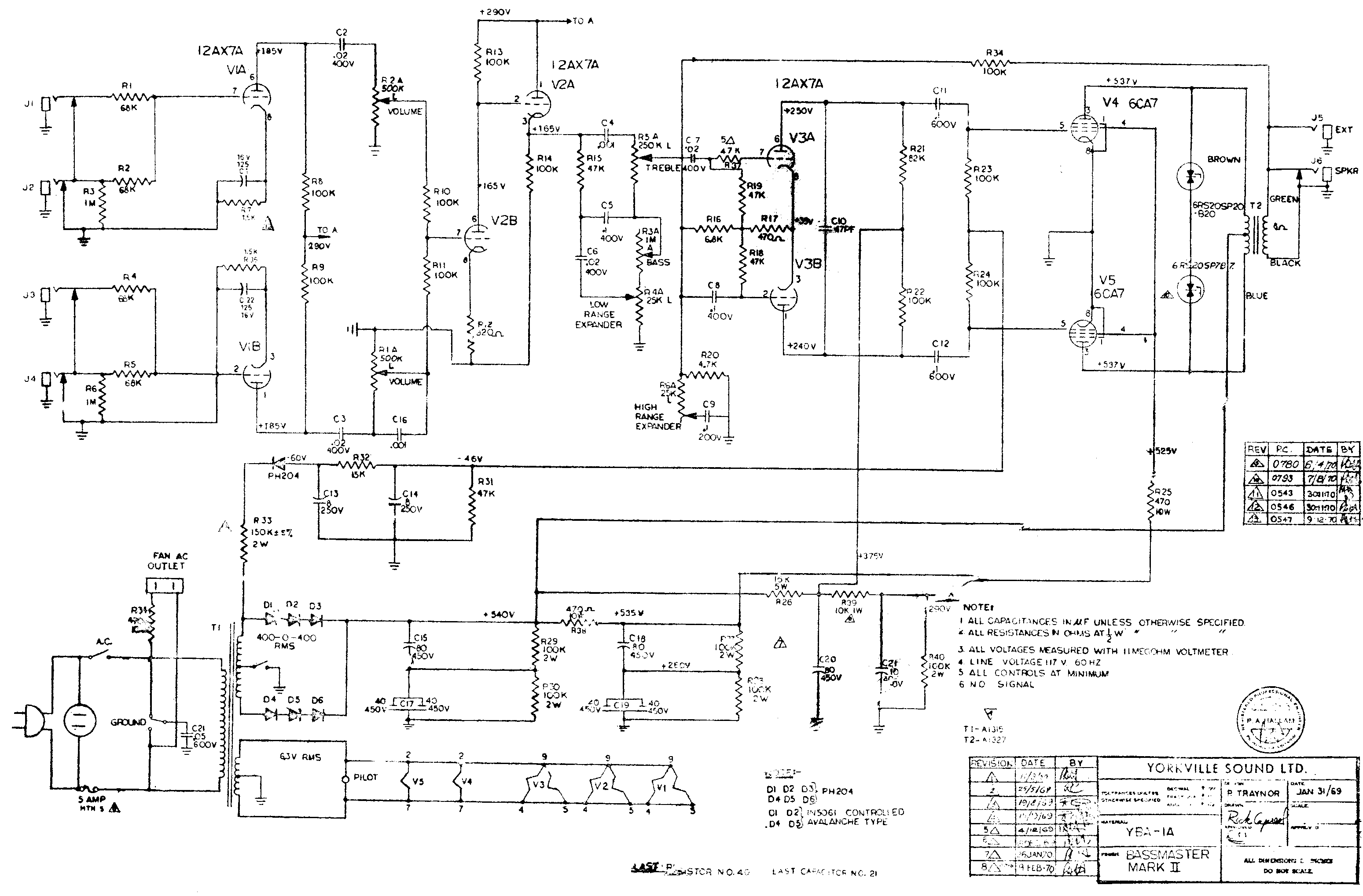
I'm working on a Traynor YBA-1A and the screens are running at around 560VDC.  This is an earlier one, and according to the schematic should be at 525 - but I am running around 122-125 VAC at my place, and according to my calculations it would've originally ran a little hot to begin with.

Heaters are at 6.9 (I think - typing this from memory.)

I really would like to bring this down to at least the factory specs, and get the heaters in line.  Then maybe try to knock the 25vdc extra off of the screens

It is blowing EL34s, and I can't really afford to just let it keep popping $40 tubes .  Clearly, 570 is too much!

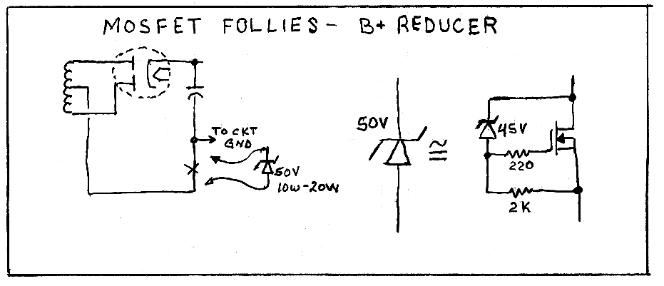
In looking around for a solution, I have come across RG Keen's  Mosfet Follies article - http://www.geofex.com/Article_Folders/mosfet_folly/mosfetfolly.htm

with the following circuit for using a mosfet power transistor on the PT CT
mosfol4.gif


The thing is, I have not worked with Mosfets and do not understand what limitations I am under/how exactly this works.  I don't know which mosfet to choose!

Is it one of these?  http://www.digikey.com/product-search/en/discrete-semiconductor-products/transistors-fets-mosfets-single/1376381?k=power+mosfet&k=&pkeyword=power+mosfet&pv588=120&FV=1140050%2C930004e%2C9300078%2C9300079%2C9300111%2C930015f%2C9300313%2C93005aa%2C9780013%2Cfff40015%2Cfff8007d%2C1f140000&mnonly=0&newproducts=0&ColumnSort=588&page=1&stock=1&rohs=1&quantity=0&ptm=0&fid=0&pageSize=25
 
Hi!  I have not done the mosfet reducer circuit either, so sorry for not addressing your question.  However, you could change the screen resistors to 1k 5W like the Marshalls.  Also, you can construct a bucking transformer to shave off voltage to the PT primary.  This would have the additional benefit of reducing your heaters.

hope that helps!
Andy
 
> working on a Traynor YBA-1A

There are multiple versions, and not like everybody remembers all details of any of them. Please point to a very-close schematic.

> screens are running at around 560VDC

That's obscene.

Also far over the 425V spec.

The 6CA7 (US EL34) datasheet shows great gobs of power with just 400V on screens. IMHO that should be your goal. Pete was just short-cutting when he didn't use a lower-V screen supply. Ampeg did similar on the VT series, then later added a whole other PT winding for lower screens.

> "B+ reducer"

I think you want a lot more drop, and you want a % of the plate voltage, not a 40V drop off the plates.

Below is big-power factory spec, and a 3/4 voltage dropper.

Multiple resistors in series because resistors may have a 300V max spec. 100K 2W because if you ever see a Fender you should be replacing 100K plate resistors with over-size parts. Gate resistor must be right AT the Gate pin, less than 1 inch.

MOSFET must be >600V, will probably be 20W or more, and should be in a convenient case. Actual current is teensy by MOSFET standards so non-issue. Actual power is ~~4W, and we need significantly higher rating. This must be on a Heat Sink. The heatsink surface is MOSFET Drain and 560V! So today you really want "full pack", the entire MOSFET (except leads) plastic-covered. Then you can bolt to chassis without messy insulators. grease, pads.

There's a gol-darn billion new part numbers and I just can't sort them. These appear suitable:
STP3NK90ZFP - 900V 3A TO-220FP - $1.07 - TO-220-3 Full Pack
STF3NK80Z - 800V 2.5A TO220FP - $1.19 - TO-220-3 Full Pack
STF18N65M2 - 650V 12A TO220FP - $2.04 - TO-220-3 Full Pack

With the lower screen you can run less G1 bias, nearer -36V adjust your bias divider.
 
unfortunately the best fix is to get a new pwr xfmr,  big bucks, pain to install

you can reduce screens by getting rid of the choke (if it has one) and putting in a pwr resistor, dropping it just a few volts can really help,

but you still have too much heater voltage which will cook tubes also,

a power resistor in the primary is dangerous and generates too much heat and ruins regulation, most primaries are wound with big wire to keep the dcr down to 5 or 10 ohms, stick a resistor in there and you negate the low dcr/transfer function,

and that choke can influence sound also,  not only does it provide better filtering for the rest of the amp, it can kick back juice to the power tubes when they get hit with some Chuck Berry down strikes,

Canada probably used 115 back then, that is why the voltages are so high, the tubes will handle the excess plate voltage, people been doing that for years, look at the Music Man with 700 volts on the 6L6 tubes, but the screen voltage is 350. screen voltage controls plate current quite a bit, just like the bias,

one option is to stick a power resistor in the cathode circuit, this will lower you plate and screen voltage by the amount equal to the bias voltage, and also prevent thermal runaway, and the compression is nice also, power might drop 40$% but who cares? that amp has big iron anyway so this might tame the beast without adding a master volume, 

put in the cathode resistor and maybe a .1 ohm pwr resistor in the heater circuit and you are good to go, solid state devices do not seem to last long in a hi-watt tube amp for some strange reason,

another option is to use a variac or install a bucking coil but i do not know how many Henries,
 
Thanks for the thoughts guys.

Sorry about the schematics - I forget there were other versions of these

traynor-yba1-1a-mkii.gif


This is the most common one, the early one without a choke.  I'm repairing it for a friend of a friend, and it is beginning to really stress me out!

He is running 118 at his place, so I think a bucking transformer would go too far.  This is intended to be a professional home studio amp and he has the set up to deal with the volume and all that comes with it.

The TAD EL34b is rated for 500v on the screens https://www.tubesandmore.com/sites/default/files/associated_files/t-el34b-tad.pdf

I rewired the screens to the marshall setup, so instead of the single 470 ohm feeding the pair, I have two  of them.  What would a par of 1K do?  It seems like that still wouldn't be enough.


I just want to get this amp where it is reliable.


> He is running 118 at his place

Sheet says 117. This is not a problem. (Anyway this and a bass-amp and some light may dip the wall to 116V.)

> I just want to get this amp where it is reliable.

Either fix it not-enough, or too-much, and see how he feels.

It is possible that "any" reduction in stress will lose some aspect of its brutal sound.

OTOH, it is hard to see how even a "a professional home studio amp" needs to work as hard as a Stadium Slammer.

In 1971, a big show in the Winnipeg cow-barn would move you up to Montreal hockey-rink or even Detroit! A few over-Volted dead tubes were the price of Stardom. While tubes are actually *cheaper* today than in 1970, we don't like constant tube replacement.

I would go even 3K on G2 resistance, taken as 2K instead of 470r R38 and 1K in each G2 lead. At full power the 2K drops ~~50V. The 1K drops some more.

However in another regular-client case (I was on salary at a school), a very similar over-volted TOO-DANG-LOUD 60W Ampeg VT40 went 20 years at +560V on the original 7027s and then burned its PT.(*) As replacements were not readily available at the time, it sat. Finally I thought to get a Bassman replacement for 400V of B+, and re-rig more like a Dynaco 35W. The school band was not playing outdoor gigs, and now mostly with PA. In fact I ended up cathode-bias at 20W-25w clean and nowhere near rating of any big bottle. 250 in cathode and 2K in screens made it very stable, and a tube short would smoke one or the other resistor making diagnosis and repair easy.

While a 1/3rd-power "fix" is not what your client would accept, I would be real tempted to try the MOSFET-drop and see if he notices. I think Pete over-reached on this one, he didn't need to run that hi-Volt. While a MOSFET adds some bucks Pete would not spend, after 45 years I think it has earned a less stressful old age. Do it with minimum rip-up, so if the sound changes, it can be made "virgin" again.

(*) This was a G2-K short, though the tube tested no-short when cold so it took a while to prove. IAC I had ordered a fresh pair of EL34 and adapted the 7027/6550 sockets to take EL34/6550/6L6GC/KT66 and even 7027. I test-ran it with 6550 on one side and metal 6L6 in the other and it played fine, though the metal 6L6 was marginally past ratings. The prof, who had not known it before the fire, was very pleased, and stole it for his studio. Never saw it again before I retired, which was my real goal.
 
How are you calculating the voltage drop for the screens?


This is something I can't entirely get my head around.  I know that the voltage will drop when the tubes are being worked, but I am not sure how much - and I'm not going to burn out another pair of EL34s to figure it out!  I'll measure this later when it is working!

Am I measuring 560v on the screens with no signal, but if I applied a signal I would see more like 540?  then dropping 50vdc would be plenty to get me in the range of the stronger 500V EL34 types


The last time the amp blew up I was actually showing it to a friend who was there to pick up his '63 AC30.  He had been playing for awhile with it at half volume, and I cranked it up loud and put a fuzz pedal on - it sounded amazing, actually more harmonically rich than the AC30 believe it or not.  But then the fireworks began...
 
do you have a scope?  look at the output signal that goes across the speaker and look for hi freq noise when you crank it with a stomp box,

screens usually draw about 5 ma a piece, so 1 K * 5 ma = 5 volts , 10K =  50 volts, etc

you need a pwr resistor as when signal is applied, ac and dc voltage across the resistor goes way up, trial and error, try different values and see what happens to your plate current,  measure your OPT primaries, say 70 ohms a piece, then measure voltage drop across them at idle, 10 volts and 70 ohms = 5 volts / 70 = 70 ma etc

you could buy a choke and run a choke input filter, this drops B+ quite a bit, some people do not like the sound, but it beats cooking EL34's,


also check your tube sockets, a lot of old amps that run high voltage can develop leakage paths that can show up when the tubes get hit hard,

ceramic sockets and some metal base Mullards would take 700 volts but that would cost more than the amp is worth so skip the Mullards and try the ceramic sockets, 5 for 10 bucks free shipping on evilbay,


Hi CJ,  I do have a scope

I didn't follow what you meant here
you need a pwr resistor as when signal is applied, ac and dc voltage across the resistor goes way up, trial and error, try different values and see what happens to your plate current,  measure your OPT primaries, say 70 ohms a piece, then measure voltage drop across them at idle, 10 volts and 70 ohms = 5 volts / 70 = 70 ma etc

The tube sockets is a good idea - it would make sense that this head blows when I hit it hard.  I've had another one of these that worked fine cranked up and at similar voltages, so this one has been really confusing, and the tube socket theory would explain it...
 
Back
Top