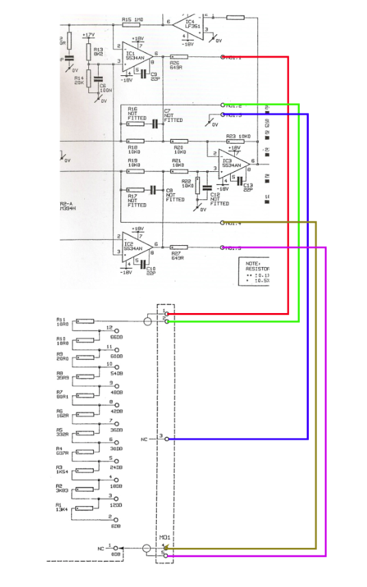
Ok there were way more issues with this circuit. The original schematic and circuits tends to oscillate at 50khz. and is way more noisy then everything i had before. I fixed this oscillation issue with adding some caps in the Gain area. Also the working point of the dual Transistor needed some improvement
")
That should compensate the oscillation problem. Also improved the input of the circuit a little against HF Problems. Now it should run smoothly. As always SSL is not just copy and Paste
i will share my changes in my documentation later on in my 4KG91 Build Guide.