joaquins said:
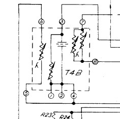
The ones with the lambda are the photocells, the others are just trim pots, that's the arrow as we have seen the trim pots drawn for the last century. The lambda was later replace for a few small arrows pointing the light sensitive device.
JS
That is interesting and it makes sense. Thanks.
I have read the various responses, links and materials about these T4B cells. I am posting a summary of my findings here so that I can reference it later. Maybe it will help others like me who are starting with no knowledge of how the T4B works. Please feel free to correct me if I misunderstood something.
The T4B consists of two Clairex CL-505L Cadmium Sulfide photoconductive cells, one for gain reduction and one for metering. Both are illuminated by the same electroluminescent panel which is driven directly by the AC input signal filtered and stepped-up to no more than ~90VAC peak. The EL panel has a 4n7 cap in series and a "trimmer" resistor in parallel. The gain reduction cell has a trimmer resistor in parallel although some earlier units seem to also have a CL-705HL 332 in parallel.
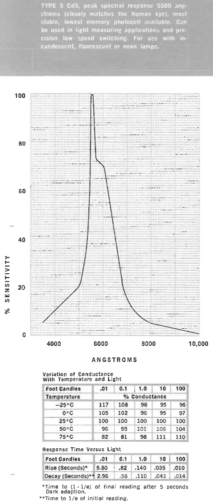
Here are some key specs for the origial Clairex CL-505L from the Clairex Photoconductive Cell Application Design Handbook:
The light and dark resistance of this cell looks like it varies between <1K to >1M in the dark.
So the Type 5 CdS are most sensitive to yellowish light and the "Rise" time is quite slow taking several seconds to fully recover. There is a huge variation in the performance of these parts so two units must be carefully selected. There is also a "memory effect". If the device spends most of it's time in the dark, the response will be significantly different from that of a unit that spends most of it's time in the light.
[Although this effect is explained in some detail in the above mentioned handbook, I don't completely understand it. But my impression is that it could be important to compression behavior. If there is a moment of silence in the input, when the input signal is restored, the cell will "remember" the previous resistance level and thus generally serve to provide a consistent signal level.]
The modern replacement part of choice for the CL-505L seems to be the Silonex NSL5910 CdS photo cell (although UA use NSL-02-042 0310). Unfortunately the new cells are measurably faster and the EL panels turn on at a significantly lower voltage and are generally brighter. Although the Kenetek part seems to be quite good they do acknowledge in their video that it is simply not possible to replicate the behavior of the original TB4 using new parts. I don't know how significant the differences are in practice.
So yet again, "better" is not always desirable.


")