Relay bypassing vs Normalizing - Signal question and patch PCB feel

GroupDIY Audio Forum

Help Support GroupDIY Audio Forum:

This site may earn a commission from merchant affiliate links, including eBay, Amazon, and others.

boji

Well-known member
Joined
Jan 6, 2010
Messages
2,377
Location
Maryland, USA
I'd first like to mention this relay rabbit-hole I've dug myself into, is partially a result of abbey road d enfer chastising me a few years ago on a poor approach to bypassing signal, saying (in so many words), "If you are going to do it [bypass something], don't cut corners and half-a** bypass... Go all teh way."  ;)

So I'd just like to get your opinions on bypassing balanced patches with relays close to signal source instead of, for traditional example, routing a signal from a console's input card to the patch panel, then back to the input card in a standard normalized fashion. 

I ask because in a console's input card scenario, having patch point options aplenty (also for 500 slot options) is good to have, but can add up to many lengths of wire,  even when nothing's being inserted...

So, would it be worth the trouble to stick relays right off the XLR inputs or at patch points on a console input card such that in a full bypass scenario, the signal runs are as short as possible?  I mean on the surface this seems logically advantageous,  and a few folks over the years have even offered small PCB's that bypass single channel balanced signal in/out, but for a console with many insert/patch points and many channels...are the added contact points in the relays, might they offset any other advantages of just using a patch bay for every point in the signal chain? I suppose there's plenty of contact points in the patchbay too, so I don't know- I honestly don't have any real-world experience using full frame console patch bays, so this might just be a reinvention of the wheel or something...

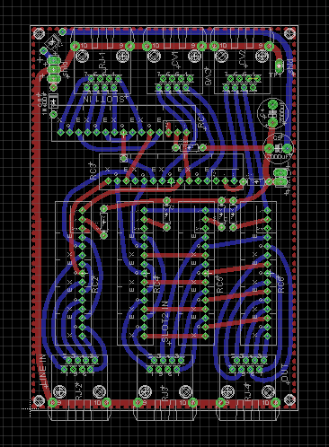
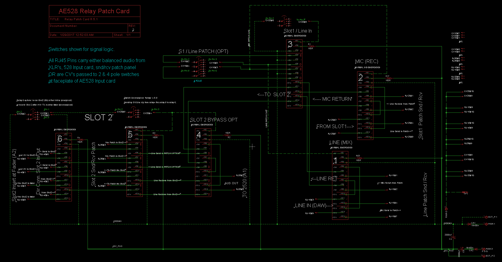
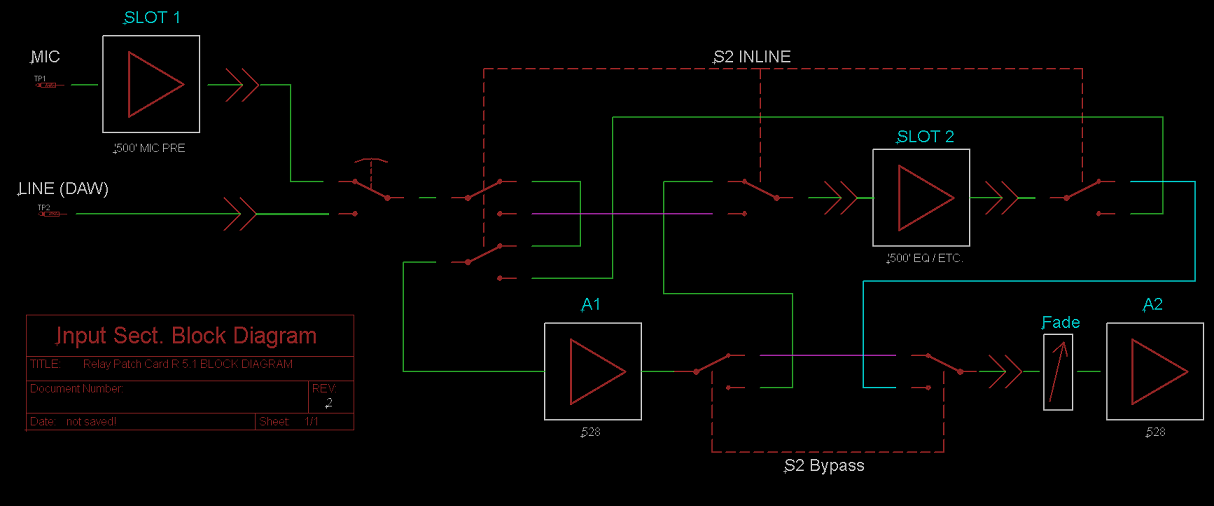
Admittedly I'm also asking as a bit of a feeler for the worthiness of a bypass patch card because I wish to put them behind my API 528-ish input cards on the diy console I'm working on.  Because I assumed shorter paths would be good, I've set about making a card also follow some button logic not unlike what is found on Tree Audio's dual 500 slot console or the Pete's Place Mark 8. This patch card would also free up PCB real-estate on the API528-ish card I've got in the works.
I'd be happy to expand on the bypass card's other uses later if there is any interest.

But first, the use/value of something like this vs keeping it simple with a full normal patch array, before I move forward?

Thank you so much yall for your advice and suggestions,
-Boji
 
  Com'on abbey! Now we have to deal with this!  ;D ;D ;D

  I won't denny I like the idea, but I think you need to make clear your objectives, what's you are trying to archive with this?
  Is there any measurable difference between hard wire the patchbay out (not connecting it, no relay PCB, just the straight wire or no wire at all on the insert point) rather than the normalized way?
  Answering that last question (doing the measurement) might answer your question, how much difference you expect doing this.

  The thing is, you are talking about low Z line drives driving relatively short wires (compared to other situations) and wire quality is superb as fixed installation last long and worth the extra penny. A 10m guitar cable means quite a lot of HF loss, even worse if level pot is not at max. Good line driver driving 30m belden cable shouldn't have an impact in the frequency of interest.

  JS
 
I am not sure I understand the problem. Mechanically there is no difference between relay bypassing and  normaling. In a 'traditional' mixer, all the inserts, inputs and outputs are brought out to an integral patch bay.  Inputs and outputs are then generally hard wired to kit in the rest of the studio so the lengths of wire to/from these patch pints are small compared to the lengths of cable from the patch bay to the external kit. For inserts, some inserted kit might be in the console and some external. Only for the internal ones is the length of wire to/from the patch bay comparable to the length between the patch bay and the kit. For external it it is the same as for ins and outs. So for the majority of connections I think there is no issue. The only ones that could have shorter cable runs are the internal insert kit.

Having said that, the only real benefit of relay inserts is the ability to easily compare processed and unprocessed signal.

Cheers

Ian
 
Hey thanks for the replies Joaquins and RR. In some ways the way you speak about it, does make it sound redundant, ie, not necessary. I suppose where the confusion lies is that it is doing more than just bypassing unused patch points, it would also switch between line and mic in's to the 528, as well as direct insert points of the 2nd slot in the console.

In this 2nd scenario, the option to either run SLOT1 inline to SLOT2 then to A1 at the 528 card or with a button press, have SLOT1 go to A1 and SLOT2 patch in between A1 and A2 in the 528-- this second way is how it is traditionally done in the API schema. The EQ driving the fader.

Perhaps I should just risk the ridicule and post the 'schema'. :)
 
I guess also an area of concern is that, from what I've read, the EQ in an traditional 1604 type console, if bypassed, did not really bypass the 2520's. They still took on the job of driving the fader even if the eq filters were not being used. So if I wish to have Slot 1 and Slot2 running inline,  I suppose I need to know if  A1 in the 528 is going to sufficiently drive the fader.  But this really does not have to do with the thread title!  :)  Thing is I figured an inline scenario approach would work when designing this relay PCB because When I take a look at CAPI's 'missing link', it appears this is the case- you have A1's TX out going directly to a stepped concentric fader, then to some buffers for the filters, then to A2 and its subsequent output TX...
 
Here's the layout.  .sch to follow.  By the way from now on I'll call the PCB that this relay card pairs with an 'AE528' so people don't think I'm actually talking about a vintage 528 card. I should also mention this PCB is for 1 channel only! I would have four in a row, stacked two high for a total of 8 cards per bucket in the console. (8 channels of AE528 in each bucket)

JcV4QLN.png
 
Sorry about the size and hard to read pin names.  I'm just screen printing directly from eagle.

In case you're wondering about the switches, explanation is in blue on the schema.
Switches are only there to make it easier to understand what's going on.

Empty pins on the switches are for indication led, except for the 4 pole which leaves one pole unused.
Relay circuits are the API zener type where CV is negative pulldown. The relays are energised when CV is absent.

QlpGRXJ.png


As you may notice there's a bit of simple logic going on here, ie if you push the switch above the relay marked  "3 " signal will come from line (mixdown), and the mic input will go to the patch so you can route it elsewhere. Conversely, if you unpress this switch, this chooses the mic in (rec), and the line in goes to the patch panel.  However if want your active selection to ALSO go to patch panel then pushing the button to the left of relay '3' will let you put either the mic or the line (whichever is activated) to the patch panel. Leave this button unpressed, and the signal remains inline, bypassing the patchbay and going on to the SLOT2 option.

Slot 2 option is a bit like the above explanation except the choices are either
Inline SLOT1-->SLOT2-->A1 or if unpressed,  SLOT1--->A1--->SLOT2--->A2

I welcome your questions, advisements or ridicule for overthinking patching. :))
 
boji said:
Here's the layout.  .sch to follow.  By the way from now on I'll call the PCB that this relay card pairs with an 'AE528' so people don't think I'm actually talking about a vintage 528 card. I should also mention this PCB is for 1 channel only! I would have four in a row, stacked two high for a total of 8 cards per bucket in the console. (8 channels of AE528 in each bucket)

I *love* the curvy traces on your PCB layout. Which PCB layout software do you use?

Cheers

ian
 
ruffrecords said:
I *love* the curvy traces on your PCB layout. Which PCB layout software do you use?

Cheers

ian

I bet eagle and tons of smoothing curves, I've done a few like that, easier to self etch than pointy turns...

JS
 
Thanks RR. Yes , Joaquin is right on the money. 

Just extra time. Set your angled trace point to point, then curve them out with 'Miter' tool in Eagle.
 
"So if I wish to have Slot 1 and Slot2 running inline,  I suppose I need to know if  A1 in the 528 is going to sufficiently drive the fader."


Update: A few days after I posted this question I received some help from a very kind owner of a 1604 and he explained that yes, when you remove a 550 from the console, the backplane connector shorts the wires, effectively putting A1 at the fader.

That's a nice confirmation since I already sent out the cards to be fabbed.  :)
 

Latest posts

Back
Top