4U or 5U 500 series frames

GroupDIY Audio Forum

Help Support GroupDIY Audio Forum:

This site may earn a commission from merchant affiliate links, including eBay, Amazon, and others.
Hi Ian,

Please see attached sketch.

You would normally be  interested in the distance B, which is from the front face of the rack (or the rear face of the module front panel) to the insertion depth of the card edge connector.

However, based on the 500 depth and the existing card edge connector,  the distance A is 155.27.  We can have this to be variable. I have dumped my previous method of making it as there is a simpler way by using spacers which are mounted onto the connector panel. Varying the height of the spacers we can vary the depth of the edge connector backplane.

Simple question is, what would you like the distance A to be?

On the other hand, since we are not using the type of connector used in Eurorack how are you going to reconcile with that?

Edit: I have also ordered the sample for a 72 way card edge connector. It has much smaller pitch, hence overall length and much higher DC withsanding voltage (1000VDC) and contact current rating (16A @25 degreesC).
 
If using a 500 series style connector, then I would suggest 173.6 mm for the A distance if using a 160 mm PCB. The extra 13.6 mm is close to the center of the range if using a DIN style connector. Plus it would be about .380" max length for the edge fingers.  In practice can use .340" to .350" to account for tolerance and it's pretty close to ideal.
 
I am not putting my foot down for 500 series edge connector (3.96mm pitch).  As I mentioned before I have ordered a sample for 72 way , 2.54mm pitch.  Specs attached.
 
sahib said:
Hi Ian,

Please see attached sketch.

Simple question is, what would you like the distance A to be?
The euro card spec for distance A is 2.54+160+12.7=175.24mm. However, in the eurocard spec, there is a 2.54mm gap between the front face of the PCB and the rear face if the front panel to allow for the standard front panel to pcb mounting hardware. I do not know if there is an equivalent for 500 series .
On the other hand, since we are not using the type of connector used in Eurorack how are you going to reconcile with that?
[/qoute]
I plan to use your backplanes if I can also persuade you to include eurocard compatible mounting holes, and upgrade all my designs to be compatible.  I am really keen this should become a new standard because,  if it can also support eurocard sub rack mechanics, it can be used to build mixers as well as rack units.
 
Ian,

You have persuaded me long time ago  8)

However, my question was that we are not using Euro Card connector and how this is this going to affect your existing PCB designs.

Would I be correct in thinking that you do not want to go through re-designing your PCBs but only to modify the connector side by replacing it with fingers for edge connection?

Or do you want me to incorporate Euro Card connector as well as the card edge connector?


Cemal,

I have to redesign the PCBs anyway because the current designs will not fit into a 2 inch panel space. I need to mount all the tubes vertically rather than horizontally as they are now. I have already done this for the classic mic pretty which I managed to squeeze into a 1.5 inch panel space. However,  1.5 inches by 3U is not a good size for mixer or EQ modules. 2inches and 4U is much better.  I plan to make this my new standard and phase out the current one. The ability for people to build a rack and include a couple of my tube designs in it, yet still be compatible with semiconductor designs, is too good to miss.

So I will conform to your standard. All I ask is mechanical compatibility with the eurocard mechanics so I can use your backplanes and the same modules in mixer builds.

Cheers

Ian
 
I would think the only real important thing is an easy way to mount standard size PCB guard rails. If you use a standard 160mm guide rail, then it would seem irrelevant if we use 170mm, 200mm or whatever (within reason) for the internal distance. The PCB will still slide in and mate correctly.

We do not need the PCB itself to conform since you would design your own  PCB anyway. Am I missing something?
 
Ian,

Understood.


John,

You are correct.  However, I will also set the principal dimensions of the module and the PCB and supply that as a template.

 
john12ax7 said:
I would think the only real important thing is an easy way to mount standard size PCB guard rails. If you use a standard 160mm guide rail, then it would seem irrelevant if we use 170mm, 200mm or whatever (within reason) for the internal distance. The PCB will still slide in and mate correctly.

We do not need the PCB itself to conform since you would design your own  PCB anyway. Am I missing something?

Yes, the extrusion that holds the back end of the guide rail also mounts the backplane so the two are dimensionally interdependent. Similary, the extrusion that holds the front end of the guide rail also mounts the front panel.

Cheers

Ian
 
I an,

I have finished the mechanical layout of the rear backplane. I am now going to start to the front/card edge connector backplane. Could you please either give me a drawing of the Euro rack mounting holes or point me to the info for it?

 
sahib said:
I an,

I have finished the mechanical layout of the rear backplane. I am now going to start to the front/card edge connector backplane. Could you please either give me a drawing of the Euro rack mounting holes or point me to the info for it?

Attached is the doc I use. Pages 3,4 and particularly 5 have the info you need.

Cheers

Ian
 
Update.

Card edge backplane PCB design is almost finished. Card edge connector samples also arrived yesterday. Plan is to start designing the second backplane next week. Then send for a set of prototype.
 
If you are interested Cemal, SRS in the UK (who do the 19 inch sub-rack kit for my lunchbox project), has adjustable length card guides. They consists of two end pieces that clip into their extrusions and  a variable length piece that fits between them. The variable length piece is made either from plastic or aluminium extrusion. I think it comes in 1 metre lengths that you cut to the size required. I believe other 19 inch sub-racks manufacturers lie Schroff also have a similar product.

Cheers

Ian
 
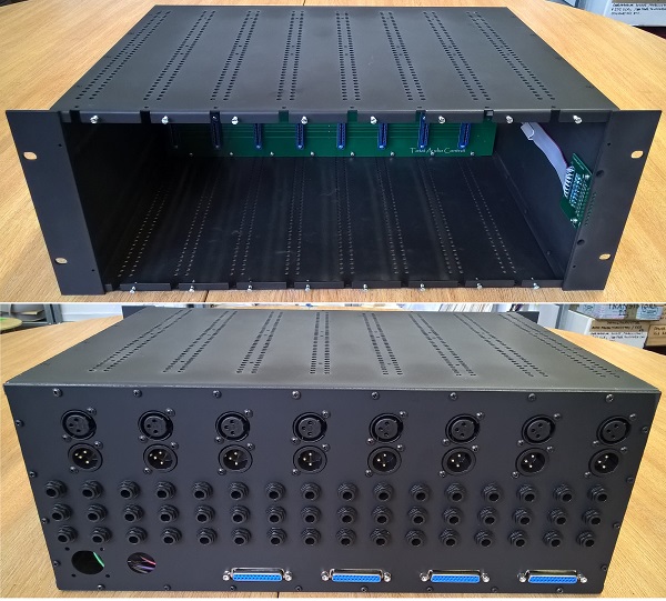
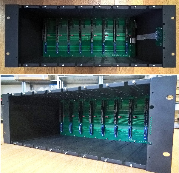
All designed and prototyped.

In fact a forum member friend has also built some modules and sent them over to me but I have been busy with other things.

I'll post pictures tonight.

 
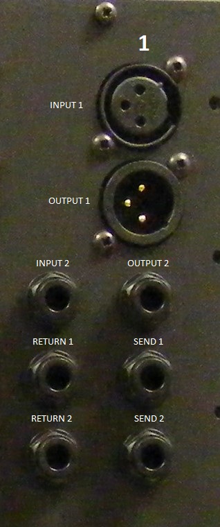
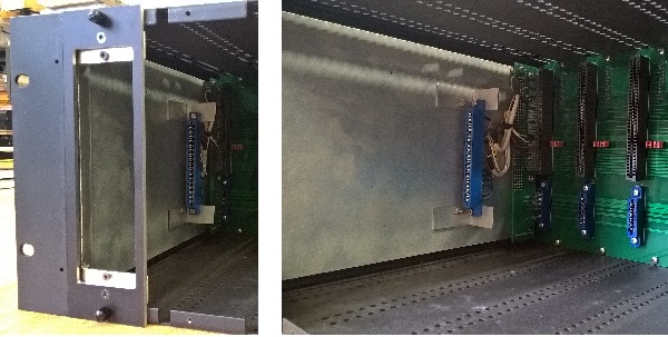
Apologies for the delay. Here are the pictures.

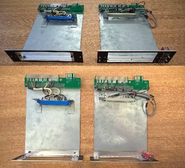
The last two pictures are showing the prototype modules made by Paul (helterbelter).  The one on the left is an adapter module to fit 500 series module.

There are  a couple tweaks I still have to make such as fitting the guide rails and the power connectors. But I have tested the signal paths on the bench and all work as planned.

If there is any interest I can look into running a small batch.

Rack428_1.jpg


Rack428_5.JPG


Rack428_2.jpg


Rack428_3.jpg


Rack428_4.jpg
 
Back
Top