1st stage of the tube amp is oscillating 50Hz.

GroupDIY Audio Forum

Help Support GroupDIY Audio Forum:

This site may earn a commission from merchant affiliate links, including eBay, Amazon, and others.

Phil smith

Active member
Joined
Jan 15, 2014
Messages
34
Location
Earth
Hey guys!

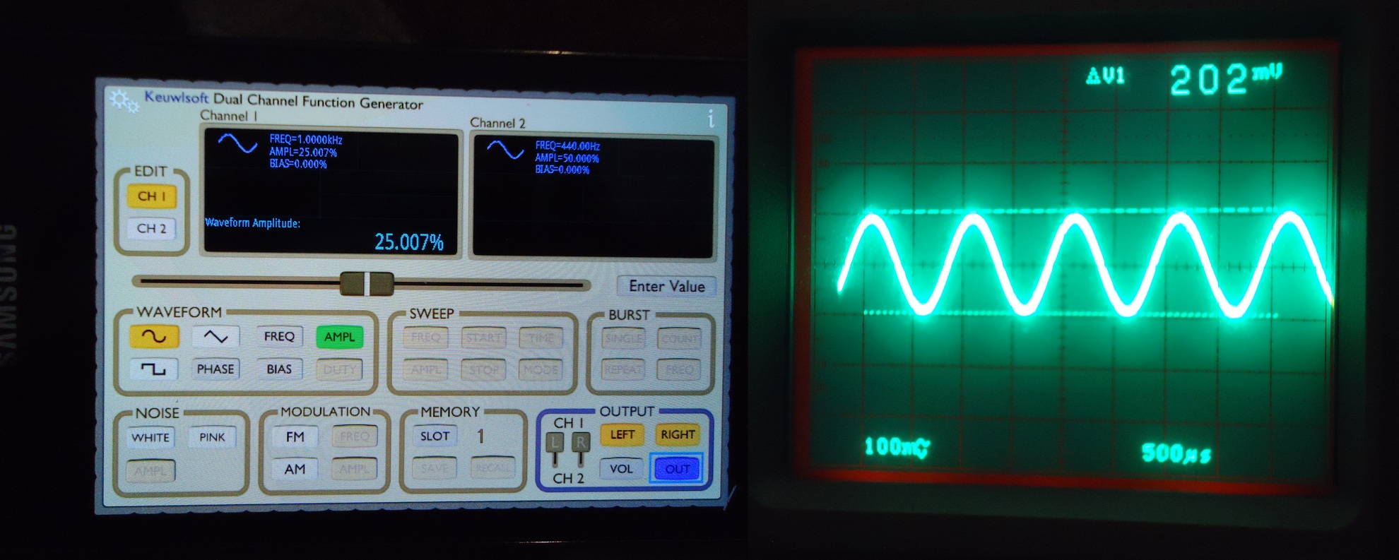
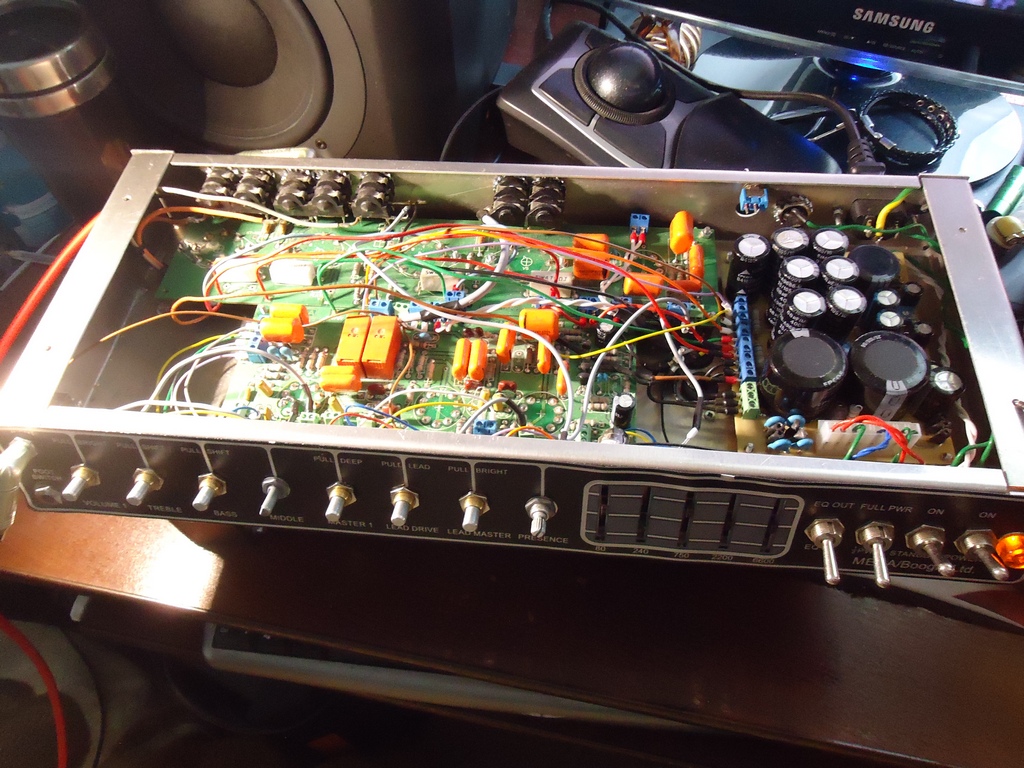
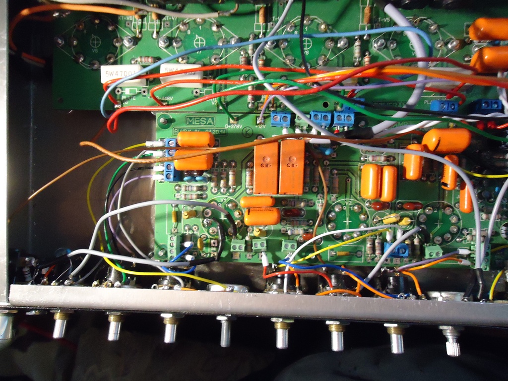
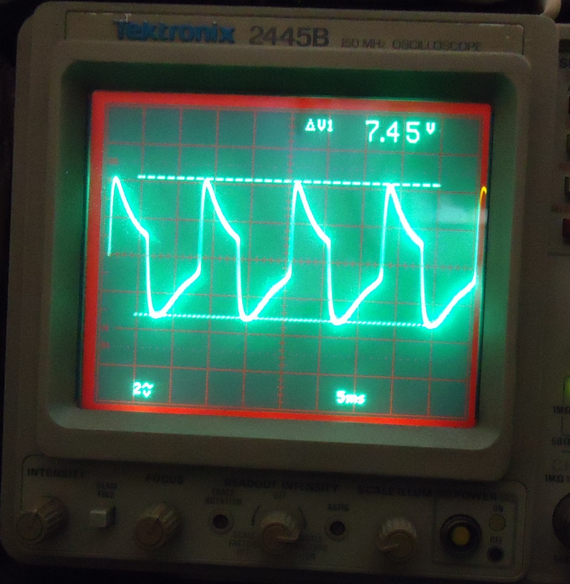
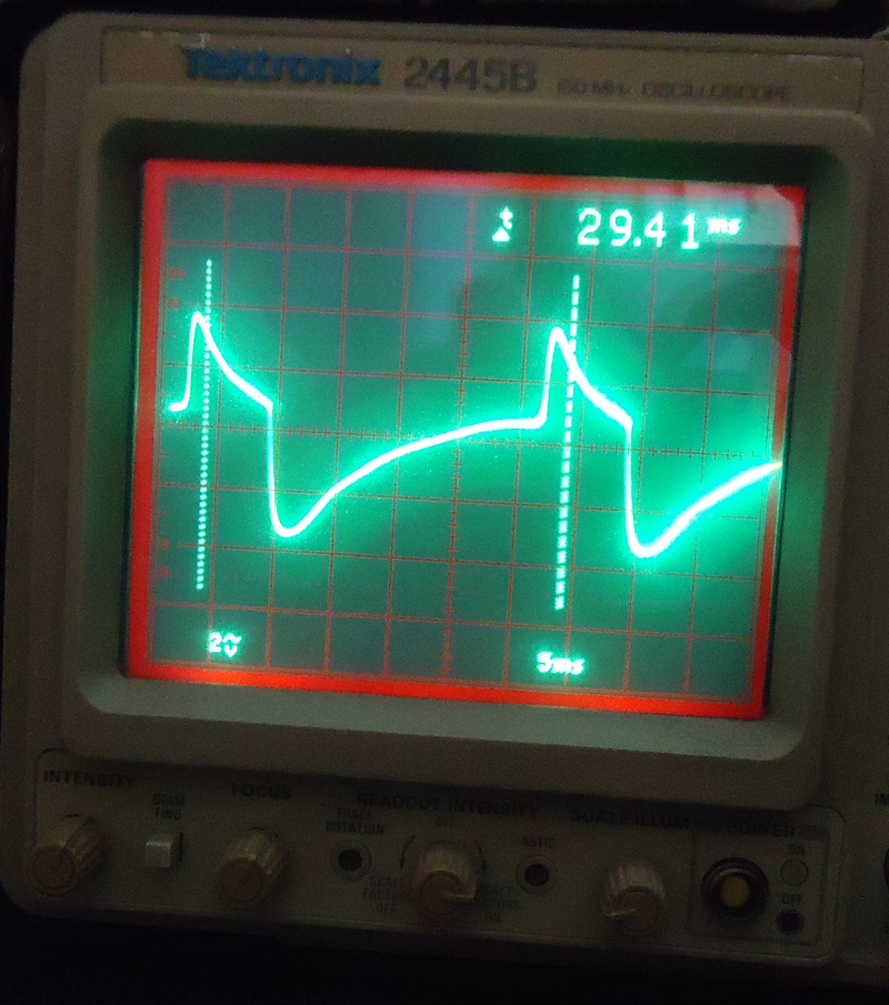
I've bee building mesa boogie mark IIc+ clone for a while. Now I've completed all wiring job, turned it on and found that 1st stage (V1-a, see circuit diagram) is oscillating like hell at 50Hz (directly on pin 1). There also 50 Hz ~1V p-p distorted sine is present on the cathode of this stage (pin 3). Test signal - 200mV p-p sine from the signal gen into the input jack.
Here's an interesting part - I can eliminate the oscillation either by turning treble control all the way right or activating "Bass shift" function which just simple bypasses 15k resistor in the cathode circuit.

I tried to swap preamp tubes but result is still the same.

So any clues what can cause this problem?

Appreciate any help!

Circuit diagram:
https://app.box.com/s/fp7y3y7zetsj41vx5mz2o8s3veivesgj


PS. All power circuit after EQ works hunky-dory, so I just disconnect power amp input after the EQ stage.

PS. PS. Should mention before - V1 is on 12VDC filament supply.

Regards,
Phil
 
50hz sounds more like a ground problem than oscillation. do you have a 1M resistor to ground in the input right? check if it is a good ground.  check also if the 12DC is well filtered. you need a big cap there.
 
Mesa use a custom cable from input to grid it have capacitance to filter RF.  They do that to not use a grid resistor. in my opinion it does not do a big difference but you need to filter RF with that cable or grid resistor.
 
12afael said:
50hz sounds more like a ground problem than oscillation. do you have a 1M resistor to ground in the input right? check if it is a good ground.  check also if the 12DC is well filtered. you need a big cap there.
Yep, I'll check 1M resistor just to be sure.
12VDC is well filtered indeed - 6800 uF before the regulator and 10000 uF after.
Power Supply diagram:
https://app.box.com/s/nqc92si6zlfld4addul7xkmmn6pz5zwa

12afael said:
Mesa use a custom cable from input to grid it have capacitance to filter RF.  They do that to not use a grid resistor. in my opinion it does not do a big difference but you need to filter RF with that cable or grid resistor.

Oh, I didn't know that, thanks!
Now I just use usual shielded cable from input jack to the pcb terminal which is almost right beside pin 2.
I should try to put the grid resistor and see what it will do
 
abbey road d enfer said:
How do you inject the test signal? What type of gen is it? Balanced, unbalanced, impedance?
Does the 50Hz happens with input shorted?

Sad to say but I generate signals with PC and sound card (in my case it's Focusrite Saffire pro 40) or using my cellphone and "Function Generator app".
For this problem it was the second option and its impedance is 50R.
I'll check shorted input version.

Yeah yeah, I know, I should get a real sig-gen  :eek: So I guess I know my next buy for my lab :D

PS. This is my first amp build, so I appreciate your critics and advises.

PS. PS. Also I'll make some gut shots for better visual understanding.
 
CJ said:
move the wires around with a chop stick (pencil) to see if it changes anything,
Tried this, no changes on the scope screen whatsoever..
Tomorrow I'll check 1M resistor and try to install 10k grid stopper and 470p cap from the grid to ground
 
mmm are you sure you have ground in your room? a computer without ground connection could charge the chassis(emi filters in the SMPS), chassis to soundcard, soundcard to amp.  if you  connect a guitar and the noise is not there then is the computer/soundcard/ground.

Mesa use other trick to reduce noise on the heathers, they use a small wire in the socket and they move the wire until the noise is minimal.

is the first stage near the power transformer??? 50hz could be induced in the tube from the power transformer if it is too close or not well isolated. the power transformer can also induce noise in the chassis if it is ferro magnetic you could try isolating the transformer with rubber washers.
 
you have some positive feedback getting into the first preamp stage,

grid stoppers will only  fix hi freq stuff,  measure your 12 VDC heater supply with meter on AC volts to see if there are any gremlins super imposed on the DC.

measure V1 DC volts, pins 1-3-6-8 and report back immediately.

 
Ok,  I've checked  1Meg input resistor in circuit and multimeter showed "open circuit", so I've made some modifications to the input jack and wire - I've disordered the resistor from the pcb and soldered 1Meg resistor directly to the jack and one more little wire to short the input when jack is unplugged.  Also I soldered 10k 1/2w resistor at the end of shielded wire and soldered it directly to the tube input pin and added  a 250p ceramic cap from grid to ground (it's been fitted at the place designated as "47p" (see pcb layout)). And and fixed the problem! But not completely..

I corrected tube pin numbers on the schismatic to match PCB layout (signal flow is V1-B -> V1-A -> V2-B -> V2-A for clean and V1-B -> V1-A -> V3-B -> V3-A-> V2-B -> V2-A for lead channel ):


Preamp/Eq board actual layout (from SprintLayout):


12 V rail is fine. DC volts directly on pin 4 is 12.115, ac volts - 100uV rms.
Actual 12V regulator is LM1085-12 (I remember I got it in my parts drawer so I put it instead of 7812), So I corrected PSU diagram as well:


Now, DC volts at 1st tube:
Pin 6 - 217 VDC;
Pin 8 - 1.76 VDC;
Pin 1 - 257 VDC;
Pin 3 - 2.03 VDC.

Here's my test signal generating via cellphone app (combined two shots - phone screen and scope waveform from the pin 7):


Overall gut shot (Power xformer - all way right, output xformer - all way lest left):


And preamp pcb (In bottom lest corner you can see input jack and 1M resistor):


So, back to the problem. Now I hot weird osculation at the pin 6 (first plate) even then the input is grounded (jack is unplugged), but frequency of oscillation changes with tone stack pots.


1st scope shot - no signal, input is grounded, volume pot all way up, bass and mid - 12 o'clock, treble pot all way down:
F = 83.3Hz, A = 75 Vp-p (it's 10x probe here):


2nd scope shot - all settings the way, but bass all way up (right):
F=33 Hz, A = ~75 Vp-p.


And if I press hard on the face plate or TB pot shafts I can eliminate this oscillation.. Hmm.. Perhaps a bad solder joint or component?

Thanks guys,
Cheers!
 
tube voltages look ok,

what about pot grounding, do they make good contact with metal? we do not want any paint or anodizing on there,  try soldering a ground buss to all the pot bodies and grounding the wire,

try it with a guitar to make sure it is not your test setup,
 
CJ said:
tube voltages look ok,

what about pot grounding, do they make good contact with metal? we do not want any paint or anodizing on there,  try soldering a ground buss to all the pot bodies and grounding the wire,

try it with a guitar to make sure it is not your test setup,

pots' cases do make good contact with the chassis - I checked em all with DMM in continuity mode, last pin of the tone stack - "MIDDLE" pin 3 also makes good ground connection.

Yep, I plugged the guitar and the cab - result is still the same - awful buzzing at frequencies, to my hear,  within the range I saw on the scope - 80-300 Hz. When I push the face plate and play open stings with another hand - buzz disappears, but I got very slow attack - so I play a note - and amplitude starts slowly increasing.
[I know something else wrong in EQ circuit, because I get strong signal before and quite weak amplitude after it. So eq could be a cause of slow attack, but I guess it's no related to 1st stage problem]

PS. I should probably record direct signal from the send jack for better understanding

PS PS - Jeez, these bloody intermittent faults.. :eek: I managed to find one cause - heater twisted pair ran to close to coupling cap - I've moved it aside, and part on the noise disappeared.. I hope.. Still poking around :) There is defiantly a  bad component/joint
 
Yey!
I managed to eliminate this problem! There were just a bad solder joint and 2 unshielded wires from Master and one from Lead drive pots. 
Now everything's good and sounds killer! 8)
One last thing - to understand eq sliders, cause it's last piece that doesn't work properly now.

Thank you all for help!

Cheers!
 

Latest posts

Back
Top