


tardishead
Well-known member
Having restored a few Compact organs one thing that very rarely survives is the original reverb tank
It was made with piezo disks not magnet/coils.
Both sides of a 12ax7 tube were used to get a big voltage swing needed for these piezo tanks.
I was wondering about different options to power a replacement Accutronics style spring reverb tank.
There is a 8vdc supply available which supplies about 110ma to all the circuitry of the organ
And then there is a 210VAC winding off the transformer which supplies 270VDC for the two 12ax7 tubes with an idle current of 1.5ma or so. One 12ax7 is used for reverb driver one for output preamp and reverb recovery amp.
So one option would be to power a LM386 reverb driver from the 8vdc.
But I was looking at this circuit from Valve Wizard. Seems like a waste to not use the unemployed tube socket and would be great to replace the reverb driver with a tube powered one.
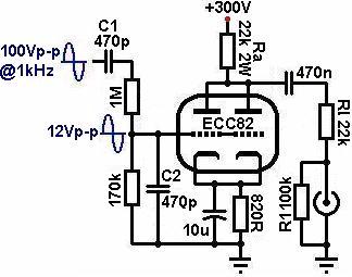
Idle current for the 2 halves of the 12au7 is stated as 6ma with peak I of 12ma
Filament current for 12au7 is the same at 300ma.
Would this be a risky modification in terms of available power from the HT winding? Which was only meant to power a couple of ma from 12ax7 tubes? But its only 2-3 more VA demanded off the transformer core which Im sure must have been built with a fair bit of headroom. Then theres the HT winding wire diameter - that will limit the available current obviously! What was general winding practise? Is this risky?
It was made with piezo disks not magnet/coils.
Both sides of a 12ax7 tube were used to get a big voltage swing needed for these piezo tanks.
I was wondering about different options to power a replacement Accutronics style spring reverb tank.
There is a 8vdc supply available which supplies about 110ma to all the circuitry of the organ
And then there is a 210VAC winding off the transformer which supplies 270VDC for the two 12ax7 tubes with an idle current of 1.5ma or so. One 12ax7 is used for reverb driver one for output preamp and reverb recovery amp.
So one option would be to power a LM386 reverb driver from the 8vdc.
But I was looking at this circuit from Valve Wizard. Seems like a waste to not use the unemployed tube socket and would be great to replace the reverb driver with a tube powered one.
Idle current for the 2 halves of the 12au7 is stated as 6ma with peak I of 12ma
Filament current for 12au7 is the same at 300ma.
Would this be a risky modification in terms of available power from the HT winding? Which was only meant to power a couple of ma from 12ax7 tubes? But its only 2-3 more VA demanded off the transformer core which Im sure must have been built with a fair bit of headroom. Then theres the HT winding wire diameter - that will limit the available current obviously! What was general winding practise? Is this risky?