Buses Driving Tips

GroupDIY Audio Forum

Help Support GroupDIY Audio Forum:

This site may earn a commission from merchant affiliate links, including eBay, Amazon, and others.

user 65064

Member
Joined
Mar 20, 2017
Messages
24
Hello guys, I hope you're enjoying a nice Sunday!

I would like to ask help from the forum since I'm currently designing a summing mixer trying to lower noise and distortion as much as I can.

Each preamp section must be able to drive 9 busses that direct it to inverting nodes of summing amplifiers (1 for master + 8 for subs) and it's feed by a pot with a "worst case source res." of 1.25 kohm.

To achieve an optimal noise performance resistor that are not feed by the preamp signal are grounded and so the load remains constant.

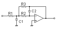
Using  4 kohm resistors their parallel results in a load of around 450 ohm, my set up involved the use of a parallel configuration using 2 x Opa2134/2 as buffer (see attached file).

Since they are rated to be able to drive a 600 ohm loads, I guess that paralleling them for a load of 450 ohm would be good regarding THD performances and considering the - 3db noise advantage of this config.

I guess the source of 1.25 kohm wouldn't be a problem causing heavy distortion considering the doubled input capacitance of these FET devices, they are rated to work well below 2 kohm sources without compensation, any advice regarding this?

Should I consider a doubled source res. feeding any single op amp?

Setting a bootstrapped configuration may worth or would it be a minor benefit?

Anyway I'm wondering if a push-pull set up involving a single Opa134 (compensated) would be an alternative solution (see attached file) regarding noise performance and distortion.

Any further advice is welcome!

I thank you for your time and I wish you a nice day!  ;D

Best.


Herva
 

Attachments

  • 18601434_10211865123055869_2104129062_n.jpg
    18601434_10211865123055869_2104129062_n.jpg
    89.8 KB · Views: 50
Lowest noise and distortion tend to work against each other. All amplifiers create more distortion when driving lower resistance loads but low bus resistance leads to lowest noise. You current circuit grounds the bus feed resistor when the bus is deselected. This has the effect of adding load to the driving amplifier. The only effect is to increase the load on the amp an increase its distortion. The normal way to disconnect bus feed resistors from a bus is at the amplifier end not the bus end as in your schematic You still get the noise benefits but you avoid unnecessary loading of the amp. If all buses are selected you still need to drive 450 ohms. I think this is excessive. You will be fine with 10K bus resistors which will lighten the load on the amp and reduce distortion and you will only need one amp. The noise in a 10K resistor is a mere -117dBu. Bus resistors are generally not a significant source of noise in a mixer.

By the way, there is no double 's ' in buses.

Cheers

Ian
 
ruffrecords said:
Lowest noise and distortion tend to work against each other. All amplifiers create more distortion when driving lower resistance loads but low bus resistance leads to lowest noise. You current circuit grounds the bus feed resistor when the bus is deselected. This has the effect of adding load to the driving amplifier. The only effect is to increase the load on the amp an increase its distortion. The normal way to disconnect bus feed resistors from a bus is at the amplifier end not the bus end as in your schematic You still get the noise benefits but you avoid unnecessary loading of the amp. If all buses are selected you still need to drive 450 ohms. I think this is excessive. You will be fine with 10K bus resistors which will lighten the load on the amp and reduce distortion and you will only need one amp. The noise in a 10K resistor is a mere -117dBu. Bus resistors are generally not a significant source of noise in a mixer.

By the way, there is no double 's ' in buses.

Cheers

Ian
Hi Ian and muce thanks for you answering!  :D

If may be possible could you please send a drawing of how you would disconnect buses?

I decided to ground resistor in this way to lower noise gain and switches capacitive cross talk as much as possible.

I know that the down side of this routing is that the load the preamp has to drive is quite heavier, anyway I stated that a parallel of 2 x Opa 2134 / 2 were able to drive 450 Ohm more than decently since the datasheet rated a THD of 0.00015% (G=1, f=1kHz, Vo =3Vrms) with a single unit driving a 600 Ohm load.

Each Opa 2134 / 2 sees a "virtual" load of 900 ohm so I assumed that this loading would give a THD somewhat better than the 600 Ohm loading, resulting in a really good THD performance, am I wrong?

By the way I would like to keep resistors value smaller to lower cross talk too.

I'm adopting a redundant approach (paralleling op amp for buffers + devolved summing system) to lower noise and increase the drive capability.

I was wondering if adopting an hybrid configuration was a better design (push-pull or whatever).

Best.


Herva

ps. Buses spelling now is correct, thanks!
 
  If you switch the other side the resistor remains connected to the bus, in which case, if you short it out you get worse noise gain than needed.

  If not you could leave it open, but that's not good practice either, as it can pick up dirt to the bus or radiate if leave connected only to the opamp out.

  I think the third choice could be short it across itself, preferably switching at the bus side with the switch as close to the bus as possible, that's why remote switches are common. to minimize the bus capacitance.

  About the bus capacitance, if it's creating an issue, a Jensen OLI (parallel RL, 33Ω 33µH or there about, or a 33Ω 1W carbon resistor with 30 turns around it, give or take, I don't remember the exact numbers) helps to decouple capacitive loads and bus capacitance to improve stability.

JS
 
Stability is a serious issue with op amp based virtual earth mixers. it is usually possible to ensure stability with a known number of sources. One problem with disconnecting bus resistors (however you do it) is that the number of sources is now a variable and, although lower noise gain is a benefit, worsening stability is a consequence. The problem arises because op amps have a large fixed open loop gain. This means the amount of negative feedback (which determines stability) depends on the number of sources connected and it increases with fewer sources. Increased negative feedback worsens stability.

There is a solution to this problem - it is called a transamp. Essentially this is a specially designed op amp whose open loop gain increases  with the number of sources connected.  The idea is to keep the difference between the open loop and closed loop gains (which is by definition the amount of NFB)  almost constant so the system is stable no matter how many sources are connected.

Cheers

Ian
 
A lot of this has been discussed in detail..  I wrote an article about in in 1980 (RE/P magazine). http://www.johnhroberts.com/des_art_1.pdf    (Caveat Lector I wrote this article over 45 years ago, but it mostly holds up OK. One glaring error I spelled bus wrong myself back then...  :eek:  )

Let me give you the short answer first. The noise from one microphone input boosted to reasonable level will swamp out the noise of any reasonably executed sum bus circuit.

There are many micro-optimizations that often trade one spec for another.  Another observation is for large bus structures (I've done consoles that summed more than 100 stems), the more apparent signal degradation is from phase shift, not summing noise. While noise may be more audible, phase shift is still an error. Distortion increases due to the same mechanism (loop gain margin). This is absolutely not a concern for modest sized bus structures (running at modest noise gain) using modern high performance op amps (with high open loop gain). 

Over the decades I made several refinements to large scale analog summing, but my advice today if you want summing as good as it possibly can be done, do it in the digital domain (sorry).

JR
 
JohnRoberts said:
...
Over the decades I made several refinements to large scale analog summing, but my advice today if you want summing as good as it possibly can be done, do it in the digital domain (sorry).

JR

Do computers know how to do a sum?  ;D

Are you saying ADC, digital summer, DAC is better than an equally well executed analog summer? I mean, if you have the analog signals and you need the sum of them, doesn't seem like a reasonable aproach.  :eek:

JS
 
joaquins said:
Do computers know how to do a sum?  ;D

Are you saying ADC, digital summer, DAC is better than an equally well executed analog summer? I mean, if you have the analog signals and you need the sum of them, doesn't seem like a reasonable aproach.  :eek:

JS
I don't know, it depends on how well you execute an analog sum bus.  ;D

If you are going to end up digital for the final product, you will come out ahead performing the sums in the digital domain.  Summing a bunch of X bit stems results in a product with more than X bits resolution (or dynamic range). Doing the same thing with a bunch of analog stems will always have a performance cost compared to the input quality of a single stem.

I do not suggest this is significant but when chasing absolute performance limits it is worth holding in perspective.

JR 
 
JohnRoberts said:
I don't know, it depends on how well you execute an analog sum bus.  ;D

If you are going to end up digital for the final product, you will come out ahead performing the sums in the digital domain.  Summing a bunch of X bit stems results in a product with more than X bits resolution (or dynamic range). Doing the same thing with a bunch of analog stems will always have a performance cost compared to the input quality of a single stem.

I do not suggest this is significant but when chasing absolute performance limits it is worth holding in perspective.

JR
  Perspective is a good thing, I'm just kidding...
  After the digital sum you end with more bits as a mathematical trick to do things easier, SNR isn't improved because you have more bits, you only have more bits to deal with. In the other hand, while using DPS the result should be pretty predictable and deterministic (given deterministic sources), doing so in a software DAW might not be the case, I've seen pretty awful results, haven't done the experience in the last few years but 5 years ago or so, you could put the signals and get different results on different software or in the same one on each bounce. Single sample peak, copied on many tracks, sampled aligned, sum could not be a single sample peak just bigger but wider peak or even different peaks all together. That's a signal that makes it pretty obvious at simple sight, other signals could be used to obtain harder-to-evaluate results.

JS

PS: dont forget that there is people doing DAC->analog∑->ADC :D
 
joaquins said:
  Perspective is a good thing, I'm just kidding...
  After the digital sum you end with more bits as a mathematical trick to do things easier, SNR isn't improved because you have more bits, you only have more bits to deal with. In the other hand, while using DPS the result should be pretty predictable and deterministic (given deterministic sources), doing so in a software DAW might not be the case, I've seen pretty awful results, haven't done the experience in the last few years but 5 years ago or so, you could put the signals and get different results on different software or in the same one on each bounce. Single sample peak, copied on many tracks, sampled aligned, sum could not be a single sample peak just bigger but wider peak or even different peaks all together. That's a signal that makes it pretty obvious at simple sight, other signals could be used to obtain harder-to-evaluate results.

JS

PS: dont forget that there is people doing DAC->analog∑->ADC :D
Just like execution matters for analog summing, execution in the digital domain matters too. While I expect it is far less of problem these days, digital audio paths were not always as refined as they are now. In the distant path compromises were likely made to account for inadequate processing headroom.

Just like analog paths need voltage headroom so the electrical signals don't saturate, digital paths need enough processing headroom so they can accomplish all the math required within the sample time window,,, 

This is not my area of expertise so I speak only in general terms but I have been watching and studying "the outside the box"  trend... if it was real I might be able to sell them better analog boxes,,,  8)  nah...  :'(

JR
 
Much thanks guys for your answers!  ;D

I'll investigate the Jensen OLI and transamp tips for sure.

Anyway here're a bit more informations, on what I'm planning.

My unit will be a 12 x stereo channels line mixer, there will be no mic pres at all (I'll wire it to synths/drum machines/samplers + audio interface outputs + outboard effects and stuff..)

I already summed in digital domain but I definitely prefer analog summing for my set up.

I'm not a purist searching for no phase distortion or zero noise, I just want to minimize this effects as much as I can since my previous mixer was a nice sounding but noisy one, this time I would like to have a quite situation.

I planned to have the mixer smaller than 10 rack units, so it will be a relative small console.

There will be no single big buses, but I'll connect every couple of stereo channels directly to the summing stage, shorting cables as possible (I decided to do in this way to have channels independents if I have to do maintenance while I want to keep using the mixer).

I'll use screened cable with max 50-60pf/m and my devolved summing system let every sub op amp to manage 4 channels (mono) at time with cables from 20 to 30cm (so I'll have max capacitance of around 20pf per cable).

Considering the switching method I proposed, I calculated a total capacitance seen by every inverting input from 80pf to 100 pf.

I think that a 100pf cap in feedback paths could be able to compensate delays in NF network, what you think?

Using Opa 2134 I should not have problem to drive these 100pf feedback caps, this Op amp with a gain=-1 and a load cap of 100pf shows an overshot of less than 5%.

Do you have any alternative suggestions for a summing Op amps?

Much thanks!


Herva
 
  The bus capacitance is for sure bigger with your approach than a single, solid wire floating in the air for example, I don't understand the advantage of doing such thing, and in the case of doing so using shielded cable doesn't seem as a good idea. 100pF from the inverting input to ground seems like a bit excessive for a small summing amp, even if you want to go for the independent wire strategy, do it with single wires running each bus together and away from the rest, to avoid capacitive coupling with the medium. The closest thing should be, in a balanced fashion, the reference from each channel to the summing amp reference, to avoid picking up more noise than necessary, it shouldn't be a problem.

  The gain of the amp is not -1. While the gain for each signal is -1, the noise gain of the amp is the number of channels plus one, so for 12 channels connected, noise gain is 13. For analyzing stability that's what you use, not the signal gain.

JS
 
joaquins said:
  The bus capacitance is for sure bigger with your approach than a single, solid wire floating in the air for example, I don't understand the advantage of doing such thing, and in the case of doing so using shielded cable doesn't seem as a good idea. 100pF from the inverting input to ground seems like a bit excessive for a small summing amp, even if you want to go for the independent wire strategy, do it with single wires running each bus together and away from the rest, to avoid capacitive coupling with the medium. The closest thing should be, in a balanced fashion, the reference from each channel to the summing amp reference, to avoid picking up more noise than necessary, it shouldn't be a problem.

  The gain of the amp is not -1. While the gain for each signal is -1, the noise gain of the amp is the number of channels plus one, so for 12 channels connected, noise gain is 13. For analyzing stability that's what you use, not the signal gain.

JS

I wanted to have every channel independent to be able to unplug them without being forced to desolder the big buses from the board, anyway your right 100pf is too much..

Since summing system is devolved I could just group channels in groups of 4 an use smaller floating buses to tie them up (unscreened and placed cleverly to reduce pick ups).

By the way I know the stability thing, I just reported the overshot datas like Opa's datasheet stated (they consider among others the inverting case / gain = -1), this op amp is good at driving capacitances.

http://www.ti.com/lit/ds/symlink/opa2134.pdf

I need to calculate the parasitic capacitance using unscreened cable anyway I think  I could reduce the feedback cap to 22pf or 15pf per summing stage.
 
Herva said:
I wanted to have every channel independent to be able to unplug them without being forced to desolder the big buses from the board, anyway your right 100pf is too much..

You still can do it, make the bus a snake with connectors for each board or a board by itself where the other boards connect to, or have short wires, plenty of options I guess. API 8200 is a mixer with all the bus running out of the rack with unscreened wire (wide ribbon interconnecting them)

JS
 
While this is a bit esoteric, I did experiment with building a 2 pole LPF into the bus amp using as topology that incororated the bus capacitance as one of the filter Cs.

OPtLowPass.png


I ultimately abandoned doing this for production but you could make the bus capacitance in parallel with filter C1, so innocuous. 

Just FYI, not suggesting you do this unless the C is really large.

JR
 
To best learn all the finer points of how to properly drive a bus, you should probably ask an expert like Ralph:
 

Attachments

  • Honeymooners.jpg
    Honeymooners.jpg
    167.6 KB · Views: 9
Thanks guys for all the answers!

JR your idea sounds really interesting, I'll keep this tip in mind for the future.

Anyway now I want to keep thing as simple as I can, I decided to go for unscreened cable as Joaquins sudgested.

I'm studying also tu  get around the bus issue using nested board that fit together using some MTA156 connector (any advice here for a good solid connector?).

Every couple of (stereo) channels will be summed on a dedicated board directly connected to them, and the final summing board will be a further layer on top of the channels summing boards.

If a find a way to make it solid I can squeeze every cm^3 from my unit.

I'll post some drawing as soon as I perfect it.
 

Latest posts

Back
Top