Bo Deadly
Well-known member
I want to do an LA3A circuit (no I/O, just the attenuator resistor network with T4B cell, EL panel driver w/ autoformer and associated controls).
The B11184 autoformer looks like a convential 5W 70V line distribution transformer:
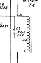
so I was going to use this from Parts Express:
http://www.quamspeakers.com/filebin/product_spec_docs/spec-pdfs/TBLU.pdf
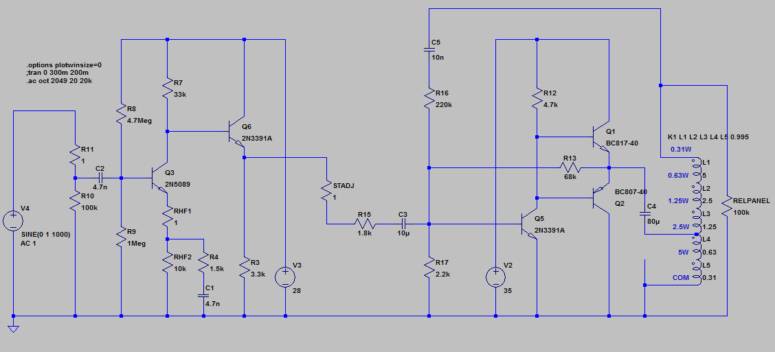
But just to be sure I understand what this part is doing I thought I would model things in LTSpice:
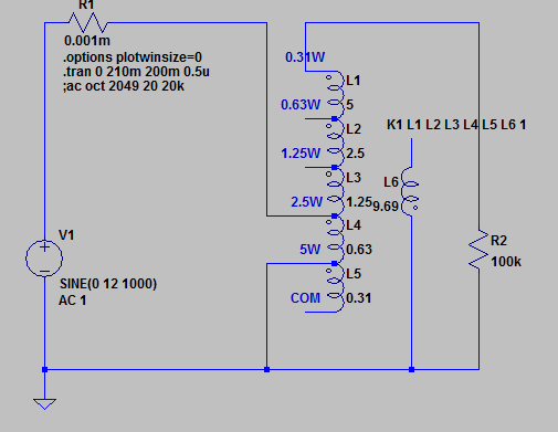
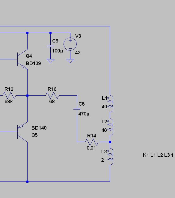
I have no idea what the real inductance values are for each tap would be for a line transformer like this but I found that using values relative to the wattage of each tap (but in reverse order) yields the right power into an 8 ohm load (meaning if I put the stimulus on the 5W tap and measure 5W power on the load and then switch to the 0.31W tap, it now gives 0.31W through the load, so it's correct).
So now I want to see what the step up is. For some reason I don't get the same results of I connect to the 0.31W tap vs using a separate winding equal to the sum of all of the windings (5+2.5+1.25+0.63+0.31 = 9.69H). If I use the tap I get a step-up of~7.25x. If I use the separate 9.69H winding I only get square root of 9.69/0.63 = 3.9x.
So using the 0.31W tap that steps up 12V to ~47V. I use the separate 9.69H winding that steps up 12V to ~87V.
So how does one model a 70V line transformer like this in spice?
Does anyone know what the step up is supposed to be in an LA3A?
The B11184 autoformer looks like a convential 5W 70V line distribution transformer:
so I was going to use this from Parts Express:
http://www.quamspeakers.com/filebin/product_spec_docs/spec-pdfs/TBLU.pdf
But just to be sure I understand what this part is doing I thought I would model things in LTSpice:
I have no idea what the real inductance values are for each tap would be for a line transformer like this but I found that using values relative to the wattage of each tap (but in reverse order) yields the right power into an 8 ohm load (meaning if I put the stimulus on the 5W tap and measure 5W power on the load and then switch to the 0.31W tap, it now gives 0.31W through the load, so it's correct).
So now I want to see what the step up is. For some reason I don't get the same results of I connect to the 0.31W tap vs using a separate winding equal to the sum of all of the windings (5+2.5+1.25+0.63+0.31 = 9.69H). If I use the tap I get a step-up of~7.25x. If I use the separate 9.69H winding I only get square root of 9.69/0.63 = 3.9x.
So using the 0.31W tap that steps up 12V to ~47V. I use the separate 9.69H winding that steps up 12V to ~87V.
So how does one model a 70V line transformer like this in spice?
Does anyone know what the step up is supposed to be in an LA3A?