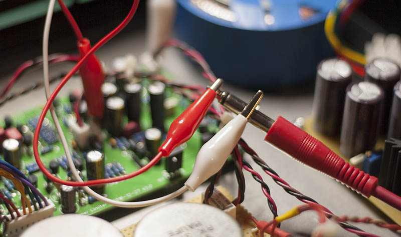
[BUILD] fripholm's TG1 Zener Limiter boards - support thread

GroupDIY Audio Forum

Help Support GroupDIY Audio Forum:

This site may earn a commission from merchant affiliate links, including eBay, Amazon, and others.
Okay, finally powered it up with out letting out any magic smoke.

So both channels are really noisy with the circuit in, very similar to radio interference and perfectly clean bypassed, I know getting through the transformer part of the wiring is fine. This happens on both channels. Channel 2 has about 15 less gain than channel 1 and when I do the fine tuning step 1 the waveform on the oscilloscope looks very different. Noise is present with BYP1 (input transformer to board) disconnected but with BYP2 still connected. With BYP disconnected it goes away. Level differences do not change with swapping transformer, BYP 1,2, input or output connections.

Transformers being used are Sowter 1295 for the input (wired backwards for 3:1, no attenuation taps) and 1365 for the output. There is +8dB of gain when compressor is bypassed.

The fancy meters seem to track pretty good and there is plenty of travel in the gain reduction trimmer to get it where you want.

The stereo linking works but when disengaged the lower output channel shows less gain reduction then none when the mode is switched back and forth. It is almost as if there is a residual charge on the gain reduction part of the circuit then it is dissipated when switching between compressor and limiter.

From what I can test, this thing gets really aggressive, but is able to sound much more smoothed out with the slower attack and Sidechain HPF.

Currently both channels have trimmers in place for R8 to do the fine tuning 1 step and socketed resistors per the BOM for R56 and R22.

I am very close to a working unit, I just need to figure out this noise issue and gain difference before I can go any further.

Thanks!

Paul
 
I forgot to mention that I am using stepped controls for everything except the release. Adjusting the output creates massive pops no matter what level is being used. This does not occur for the input.

Also on the meter there is a line below 0. The mechanical adjustment will only get you right to the actual zero line. I'm not sure if this is the correct way to setup this meter.

Thanks!

Paul
 
Potato Cakes said:
I forgot to mention that I am using stepped controls for everything except the release. Adjusting the output creates massive pops no matter what level is being used. This does not occur for the input.

You might have to use MBB switches or try adding 1M (or higher) resistors between each pin of the switch.
 
Pops generally mean there's DC in the switching circuit. This should not be the case because the output attenuator is between the blocking caps. I suppose the output stage has something wrong. Check DC voltages before and after the attenuator and see if there's any.
 
Potato Cakes said:
The diode was wired with the anode on the +V side and the cathode to the side connected to ground. I don't recall having this trouble on other builds.

In this case the cathode (the side with the black bar on it) goes to V+ and anode to GND. The other way around you essentially short out the power supply.

Potato Cakes said:
So both channels are really noisy with the circuit in, very similar to radio interference and perfectly clean bypassed, I know getting through the transformer part of the wiring is fine. This happens on both channels.

It seems, your output stage is oscillating! Try a series resistor between the output connector and the transformer primary, anywhere from 22 to 100 ohms.

Channel 2 has about 15 less gain than channel 1 and when I do the fine tuning step 1 the waveform on the oscilloscope looks very different. Noise is present with BYP1 (input transformer to board) disconnected but with BYP2 still connected. With BYP disconnected it goes away. Level differences do not change with swapping transformer, BYP 1,2, input or output connections.

Is there a level difference when the unit is in bypass?

If it's only different, when the compressor is in, then you need to do 'fine tuning step 2'. In this case, I would try and fine tune both channels (as opposed to just one, as stated in the guide) because of the large difference of 15dB - one channel goes up by ~7dB, the other is adjusted down by ~7dB.

Transformers being used are Sowter 1295 for the input (wired backwards for 3:1, no attenuation taps) and 1365 for the output. There is +8dB of gain when compressor is bypassed.

When you've successfully completed the above steps, this difference should have become much smaller. The resistors R86 and/or R87 do the fine tuning. Originally, the values of these are for use with a 2:1 input transformer.

The stereo linking works but when disengaged the lower output channel shows less gain reduction then none when the mode is switched back and forth. It is almost as if there is a residual charge on the gain reduction part of the circuit then it is dissipated when switching between compressor and limiter.

As this is a feedback compressor whose sidechain is fed by the output signal, it's normal that the quieter channel compresses less. When link is engaged, the higher control voltage takes over and controls both channels.

Again, complete the above steps and this will also go away...  8)
 
Thanks for the reply!

I had wired the diode this way as that is what I had seen on other designs and it worked for me in the past. Right now I'm running without till I sort out the rest of the issues.

I had read in the instructions regarding oscillating, but it did not think that was the sound I was hearing. I'll give the resistors ago.

I figured the gain difference was related to fine tuning step 2, but I was put off by the noise and I had thought there was a problem with the input stage of the lower level channel. Plus the way the drum tracks looked on the scope from one channel to another. And it was pretty late so my brain was shutting down.

I'll report back with my findings. Looking forward to sharing some photos and impressions.

Thanks!

Paul
 
warpie said:
You might have to use MBB switches or try adding 1M (or higher) resistors between each pin of the switch.

I thought about having to use different switches. Thought about having to use either DC blocking caps or the 1M resistors as you mentioned.

Thanks!

Paul
 
Ilya said:
Pops generally mean there's DC in the switching circuit. This should not be the case because the output attenuator is between the blocking caps. I suppose the output stage has something wrong. Check DC voltages before and after the attenuator and see if there's any.

Haven't measured for VDC around the switch but it is definitely there. This is also happening with switching the circuit in and out. It will pop on the side that is being switched then both sides will pop when switched out.

Quite maddening.

Thanks!

Paul
 
Potato Cakes said:
I had wired the diode this way as that is what I had seen on other designs and it worked for me in the past.

I'm sure you knew this, but maybe it's also interesting for others; see here for an awesome and simple explanation why the flyback diode on a relay coil is a great idea: https://www.youtube.com/watch?v=c6I7Ycbv8B8

And before you order different switches or make any other changes, try and make your output stage work properly. I have seen this circuit do the weirdest things and I spent days troubleshooting before I realized it was just the output stage oscillating.
 
fripholm said:
In this case the cathode (the side with the black bar on it) goes to V+ and anode to GND. The other way around you essentially short out the power supply.

It seems, your output stage is oscillating! Try a series resistor between the output connector and the transformer primary, anywhere from 22 to 100 ohms.

Is there a level difference when the unit is in bypass?

There is no level difference when in bypass. And it's definitely a radio station and not oscillating as I just added 100 ohm resistors per the guide. When push on either of the BYP2 connections or touch the back of the output pot the radio signal comes in loud and clear. Even the side that has the lower level will transmit the radio signal about the same level as the other channel. I swapped the connection for balanced cable from the output pot header to the stepped switch and same result. I even changed the switch to a 10k pot per the BOM and no change. The shield was attached to the side that connects to R94 which ties to ground. The Sowter 1365's that I am using for the output have a connection that ties to it's electrostatic screens but there is no change with it connected to ground or not.

I know it's something to do with what I've done, but I'm a bit stumped. I'm afraid I'm going to have to pull it all apart and stare at the board until I find something.

Until I fix this interference issue I won't be able to proceed with trying to solve the other guys. It's something obvious and stupid on my part as it usually is, but I hide my stupidity very well it seems.

Thanks!

Paul
 
Potato Cakes said:
...it's definitely a radio station and not oscillating as I just added 100 ohm resistors per the guide. When push on either of the BYP2 connections or touch the back of the output pot the radio signal comes in loud and clear.

Ok, does it sound similar to this MP3 file ?

This happens, when I un-plug the connector for the output gain pot/switch, which leaves the output stage's input open. It starts to oscillate far above the audio band at around 120 kHz (as seen on the oscilloscope) and what can be heard are some kind of side effects within the audible spectrum that sound like tuning an old radio and a lot of noise.

You are right, this can't be fixed by just a series resistor - must be something else.
 
It does make that noise when the output pot is disconnected, but the frequency shifting noise disappears when it is attached. Plus, when I touch the back of the output pot or press on the middle of the board at the output pot header, an AM radio station comes in very clear playing classic country music. I've been looking at the schematic to try to see where it could be. The only times I've had this happen is with a bad cable connection, which they all seem fine as the functions all seem to work with the exception of the loud popping in regards to the stepped output pot. I'm afraid I'm going to have to pull everything apart and start staring at solder joints....

Thanks!

Paul
 
Can you verify the correct wiring of the input and output pots? Now I have both poles (using stepped switches) going to the center header pin. I believe all other header wiring is correct as the functions sound like they are working properly.

I was hoping that I messed up the bypass wiring to the relays I am using, but those seem to be correct. I thought I had an issue with the transformer wiring, but that is also correct as it is clean when bypassed and the signal is always passing through those. I was for some reason missing R86 as that would account for the large increase in gain which didn't make sense as  the input transformer I'm using is 3:1 and the output is 1:1.7.

I'll start doing some component checking in the meantime.

Thanks!

Paul
 
Also, R66 and R71 both have asterisks by them, but no mention of why in the manual. I this something that needs to be adjusted as well?

Thanks!

Paul
 
Potato Cakes said:
Can you verify the correct wiring of the input and output pots? Now I have both poles (using stepped switches) going to the center header pin. I believe all other header wiring is correct as the functions sound like they are working properly.

Yes, the poles (or wipers, when using a pot) of both the input and output controls go the center header.

Also, R66 and R71 both have asterisks by them, but no mention of why in the manual. I this something that needs to be adjusted as well?

The asterisks are leftovers from an earlier version of the boards, which I never sold to anyone. Both resistors adjust the positive and negative subrails. If you have about +/-20 volts there, you're fine (eg. measured at the top of R28 and the bottom of R29). I never had to change these.
 
Thanks for the response. I was hoping again that I found the cause to my build woes. I think that is something related to the output pot as I get massive pops when I change settings and if this was a case of what happens with stepped output switches you would have reported this.

Whatever it is, I've manage to do it on both boards. I hope to poke around some more this weekend. I really had high hopes for this one as did some of my best soldering work on this board, so it was quite the let down when it was so noisy. If there are any bits of advice or ideas about places to check please let me know.

Thanks!

Paul
 
Have you checked for DC on the output of the compressor stage, as suggested by Ilya? What kind of switches are you using?

The topmost pin (square) of the 'outputgain' header is the unattenuated output of the comp stage. Disconnect the switch and measure - it shouldn't have DC on it.

If it does not, you could also connect your soundcard directly (turn your monitors down!!) and listen to the signal . This way the output stage is out of the equation. Is the noise already there?

Here's one easy way to do it:

alliclips.jpg
 
All righty....

Did the tests as prescribed and here's what I got.

When I first power up the device, there is about 10VDC on the unattenuated output header pin then it drops off immediately at a moderately fast rate down to about 0.01 and stays there. On power down, it does the same thing except with a negative voltage.

The noise is present with jumpers connected as described to just the unattenuated header pin and a ground reference. It is worth noting that the noise follows the compressor when there is signal at the input. When I ran program through it, the noise is attenuated with the input audio being at a higher level. The noise then returns as the compressor releases. So I believe the output stage is fine and that it is somewhere before the compressor.

The boards in the build are V2.0 and not the current V2.1.

Thanks!

Paul
 
The switches being used are Lorlin. It appears the ones I have for the output are not make before break. When I turn the switch to the point before it clicks to the next position, I get +3.5VDC at the pole of the switch, which would explain the loud pops when I turn the knob. I do have some of the nicer Elna switches, but I was hoping to save those for a mastering compressor I am hoping to build later this year. I might have to order some Grayhills.

I have a V2.1 board that I am going to use for a channel strip idea that I could build and see if I get the same results. I just don't know if I have enough parts.

I'll stare more at this guy later tonight and see if I can try to narrow down the noise even further. If I figure out the noise part, then I can finish tweaking and get my being awesome award. Like I said, it's working, it's just that something is contaminating audio before it hits the compressor stage. The noise also does not change level with any adjustments to the input control.

Of all the troubleshooting adventures I've had, this might be the most exciting.

Thanks!

Paul
 
Potato Cakes said:
When I first power up the device, there is about 10VDC on the unattenuated output header pin then it drops off immediately at a moderately fast rate down to about 0.01 and stays there. On power down, it does the same thing except with a negative voltage.

Mine also does that, when the switch is not connected, so I would consider it normal 8)

The noise is present with jumpers connected as described to just the unattenuated header pin and a ground reference. It is worth noting that the noise follows the compressor when there is signal at the input. When I ran program through it, the noise is attenuated with the input audio being at a higher level. The noise then returns as the compressor releases. So I believe the output stage is fine and that it is somewhere before the compressor.

I didn't run into this problem, but in one of the other threads about the TG someone mentioned that Zener diodes can be pretty noisy at times. However, I doubt they pick up radio stations, as in your case.

IIRC it was Ilya, maybe he can chime in.

The boards in the build are V2.0 and not the current V2.1.

Don't worry about the version number. There were only minor cosmetic changes, nothing electronics related.
 

Latest posts

Back
Top