Antique electronics experts, what is this? Transformer?

GroupDIY Audio Forum

Help Support GroupDIY Audio Forum:

This site may earn a commission from merchant affiliate links, including eBay, Amazon, and others.

vintagelove

Well-known member
Joined
Oct 26, 2013
Messages
147
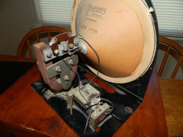
Hello and thanks for taking a look. These were in the collection of a friends uncle who passed away. He was an electronics guys who worked with lots of stuff. Unfortunately, that means these could be anything. So I come to the experts, hopefully an old timer can tell me what these are, I have a pair. As you can see they have an 1/4in jack attached to the coil? inside. Also they silver part (maybe more as well, appears to be magnetized. Thanks again for taking the time to look. Take care.


Attachments

  • IMG_0532.JPG
    IMG_0532.JPG
    994.7 KB · Views: 67
hmmm, looks interesting, don't have a clue as to what it might be,

resize pic to 600 x 800 (notebook size)>


Attachments

  • 1.JPG
    1.JPG
    175.7 KB · Views: 48
CJ said:
hmmm, looks interesting, don't have a clue as to what it might be,

resize pic to 600 x 800 (notebook size)>

Hi,

I have a bench full of test gear. What would you do if you had it on your desk to figure out what it does?


Thanks for your time.
 
ruffrecords said:
Measure the primary and secondary inductances and dc resistances for starters.

Cheers

Ian


If only I knew how...

Could you point me to a resource for measuring the inductance?

As for measuring the primary and secondary  resistance, I'm guessing the 1/4 jack is the secondary.  Where would the primary attach? The screws on the side?

Speaking of which, did you see the arrow on the side pointing from back to front?  Thoughts?


Again, many thanks for your time and wisdom.
 
It could be a 1920's (likely even earlier) speaker transducer. I've not seen this particular specimen before, but the principle looks very familiar.
Perhaps the driving rod, which is attached to the cone, would connect to the loop hole (to the right in the picture that CJ posted)?

I'm not an oldtimer, but I do work at a radio museum.  :)

Here's another:

DSCN8751_zps3150a19f.jpg


Conviction said:
It could be a 1920's (likely even earlier) speaker transducer. I've not seen this particular specimen before, but the principle looks very familiar.
Perhaps the driving rod, which is attached to the cone, would connect to the loop hole (to the right in the picture that CJ posted)?

I'm not an oldtimer, but I do work at a radio museum.  :)

Here's another:

DSCN8751_zps3150a19f.jpg


Very interesting, thanks!!?
 
vintagelove said:
Very interesting, thanks!!?

Like Ian said, measure DC resistances and pri inductance (if you have the possibility).
I'd be very tempted to hook it up to a tone generator, 600 ohms or higher.
If it's a transducer, impedance will be in the 2000 ohm range.
 
Here's an contribution from another source, fingured it would be worth adding to the thread for the curious.


Permanent Magnet Moving Coil actuator (actuates whatever is fixed to the eyelet on the bracket screwed to the core of the coil; feeding the coil with DC will build up a magnetic field in the core witch will be forced to the opposite poles of the permanent magnet; feeding the coil with AC the core will vibrate from one pole to the other - the core may only move one way since its ends are square and kept in place by guides and so does the eyelet)
 
ruffrecords said:
Measure the primary and secondary inductances and dc resistances for starters.
This is assuming there was a primary and a secondary, which would presuppose a transformer.
Not much really supports that. The whole construction advocates some kind of electro-mechanical transducer. Indeed, one is tempted to favour the notion of an early type of loudspeaker, in particular because of the not-period-correct addition of a 1/4" jack.
But it could be something else.
One of the (remote) possibilities would be an agitator for a Branly coheror. The Branly coheror was a primitive radio detector based on the aggregation of iron filings when submitted to radiowaves. It was used in telegraphy. In order to reset it after it had received a signal, it needed to be shaken.
Or simply some kind of telephone ringing bell.
 
Back
Top