FET input stage for instruments

GroupDIY Audio Forum

Help Support GroupDIY Audio Forum:

This site may earn a commission from merchant affiliate links, including eBay, Amazon, and others.

Mondy

Well-known member
Joined
Feb 11, 2012
Messages
59
Location
UK
Hello!!

Could anyone kindly check my “design by Google” preamp for acoustic guitar? I used Igor's Preamplifier's universal input board as the inspiration for the input stage as it looked ideal for the application. Igors input stage thread is here…

https://groupdiy.com/index.php?topic=31611.0

I changed the fet/transistors to those I have in my drawer (and TO92 components are pretty much disappearing, so would like to use what I have), and I plan to run the thing from an 18V battery of AA cells. I made some changes that I thought would be appropriate (in particular R4 which is R21 in Igors original design) to suit battery operation. The output will feed into an amplification stage with an input of around 3 to 5K ohm impedance

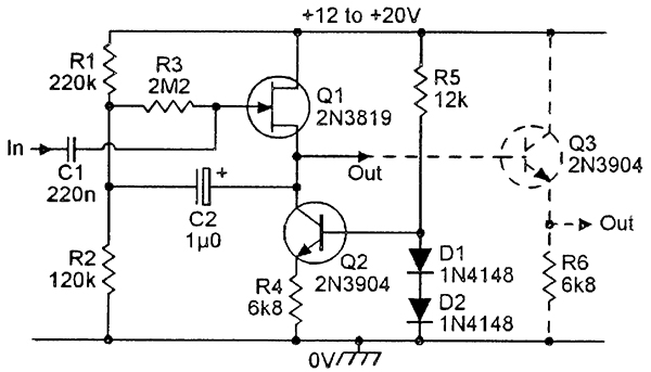
Here is Igors original design…

Igor%20FET%20Buffer%20Stage.PNG


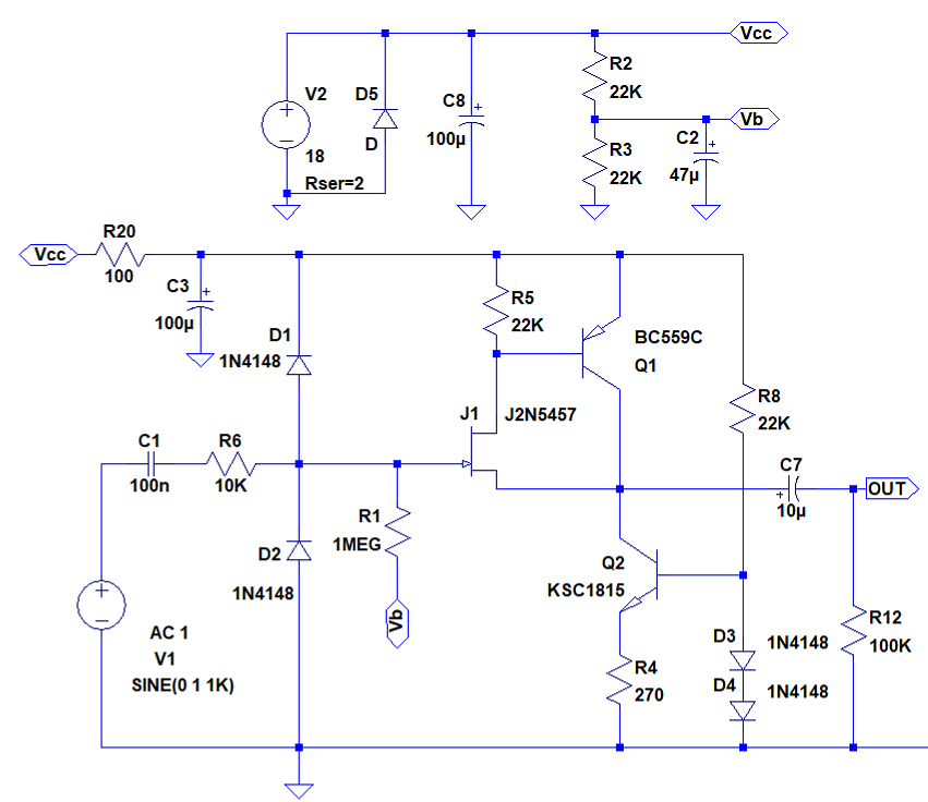
And here is my proposal.

FET%20Buffer%20Stage.PNG


It seems to sim up alright using LTSpice but could someone with a full understanding of this type of circuit let me know if I need to make any changes in resistor values/biasing to get the best performance out of the buffer stage in real life use?

Any helpers..!?  :)

Thanks
Ray
 
J1 is starved. Most JFETs, I'd run a good part of a mA to get the hiss down. R5 1K or 2K.

Slightly better gain/hiss if R6 goes after R1.

With 18V supply and reasonable guitars, Q2 et al could really be a 3.9K resistor. Saves 3 parts and 7 joints, some space.

OTOH I really would keep a few-hundred Ohm output resistor. Aside from stability issues, I have seen unlikely signals into long lines urge your Q1 to "infinite" current, which does not end well.

With R6 at 10K or more, I can't imagine the input diodes have much to do. The JFET Gate IS a diode and typically rated 10mA. With 10K in front, you are good to 100V signals forward-bias, and about the same reverse-bias. If some helper is finding 100V wires to plug into, nothing is safe.
 
Thanks for your time and advice PRR, just what I needed!

I have made the changes as you recomended and although I noticed no discernable difference in the sound, I can rest in the knowledge that the circuit parameters are now solid and can move on.

Cheers
Ray
 
OT:

here is the input section for a GK amp that we have on the bench, kind of a hassle with that 15 V aux supply,


Attachments

  • GK 700RB.gif
    GK 700RB.gif
    28 KB · Views: 170
> hassle with that 15 V aux supply,

There's also a *negative* 35V at R21. So full +/-35V, as well as -15V here, probably used other places.

Someone wanted huge headroom in the front end.
 
yes it's a bass amp, those bass pickups put out a lot of juice, especially the active ones,

there is a pad but after the first stage,

they are running those fets right on the max v spec, J113 obsolete so we used J201 which has 5 more volts max V (40  and -40)


PRR said:
J1 is starved. Most JFETs, I'd run a good part of a mA to get the hiss down. R5 1K or 2K.

If my eyeball is correct, Q2 will wiggle up and down to try and maintain the drain voltage at near DC, which sets a constant current through R5. If R5 = 1K, and the DC bias current is set to 0.7mA or below, doesn't this force Q1 off always?  It's also not clear to me how Q1 is helping (even assuming the bias works out to turn it on) - even if gain is 1, the gate would need to be driven with one hell of a voltage swing to place the output up near a +24V rail.

This topology makes more sense to me, as the output current wouldn't be limited by what Q2 can sink (aka a lower impedance load):

NV_0600_Marston_fig8.jpg
 
PRR said:
> hassle with that 15 V aux supply,

There's also a *negative* 35V at R21. So full +/-35V, as well as -15V here, probably used other places.

Someone wanted huge headroom in the front end.

FWIW, here's a single 9V rail version, taken from a Boss pedal (BD-2).

Note this section appears after the usual Boss input-buffer, so for 'naked' use directly after a passive PU,
you might want to increase R22, R23 (so that these both together result in ~1MOhm)

Regards
 

Attachments

  • bossbd2_FETDOA.jpg
    bossbd2_FETDOA.jpg
    94.6 KB · Views: 91
> If R5 = 1K, and the DC bias current is set to 0.7mA or below

But pull-down current source is shown as 0.6V/270 or 2.2mA.

Q1 FET pulls a nearly constant (0.60 to 0.66V)/1K or 0.60mA to 0.66mA, reducing distortion. Q2 swings 2.2mA +/- load current.

At 18V supply this scheme will pull up to around 15V (depending on FET choice) and down to 1V. +/-7V. Since bias current is 2.2mA, it can do this for loads down to 7V/2.2mA or 3.2K. Q2 swings from zero mA to 4.4mA. If the FET were asked to swing this much, it would have troubles. The BJT can swing it. The BJT's distortion is majorly reduced (about 150:1) by NFB to the FET.

Yes, if you wish to run lower bias current yet retail low hiss you will have to sharpen your pencil, to keep JFET current reasonably high (several tenths of a mA) for low hiss.

Your proposed plan at Out1 has only 0.6V/6.8K or 1/10mA pull-down, and would only drive full voltage into >80K. At Out2 it has a 6.8K resistive pull-down, and not optimally biased for large swing. At 18V supply, Q3 emitter sits at about 6V, has only 1mA of bias. Maximum output is about 3V into 7K (rather disappointing for 18V), about 1/4th the power output of the other plan.

> hell of a voltage swing to place the output up near a +24V rail.

18V on the plan I was looking at; but same difference. A unity-gain amp WILL need big voltage swing to justify a high rail voltage.
 
> taken from a Boss pedal (BD-2).

Minimum gain about 15. On 9V supply, this WILL distort on hard-slam guitar. Not, with those values, an all-purpose *clean* buffer.

> taken from a Boss pedal (BD-2).

OK, that is a "Blues Crunch" distortion pedal, so a little pre-clip is part of the design.
 
PRR said:
Minimum gain about 15. On 9V supply, this WILL distort on hard-slam guitar. Not, with those values, an all-purpose *clean* buffer.

You're right, for clean it sure requires re-dimensioning. Was triggered w.r.t. the 2FET+1BJT topology CJ posted.

As known, take one FET away from the differential pairs of these schematics,
and we're in essence back to the CFP/Sziklai 2 device 'opamp' topologies - in simpler form (without the current sources) as earlier in this thread

... as for instance in the Jensen applications (AS004 &  AS098, attached).

The latter runs on 9V, re-dimension that one for unity gain (like in the former, AS004) & lower the Rin.

Bye
 

Attachments

  • as098.pdf
    11.3 KB · Views: 40
Whoops said:
Is it for a piezo pickup?
if so make sure the input impedance of the preamp is around 10 Meg

No affiliation with Jensen etc, but then for instance that AS098.pdf circuit attached above would fit (10MOhm),... ignore my earlier comment of lowering the input impedance.

Bye
 

Attachments

  • AS098.JPG
    AS098.JPG
    87.7 KB · Views: 128
clintrubber said:
No affiliation with Jensen etc, but then for instance that AS098.pdf circuit attached above would fit (10MOhm),... ignore my earlier comment of lowering the input impedance.

Bye

Thanks for this!  I'm starting to work on a preamp rig for my acoustic set up and this looks perfect!

I was going to start another thread, but since this is close I can chime in here...

I bought a stereo PUTW #54 SBT (piezo film strips that glue to the bridgeplate, sound board transducers).  These have very low output, so I am thinking of setting up a small box that will plug into the guitar and have each of the transducers hit one of these preamps, which would output to a blend knob, and then use a 4 pin xlr to run a 4 conductor cable to a floor box that would have a second gain stage, an inductor eq (something like the NY Dave passive EQ), then a final gain stage, with a power supply in it (hence the 4 conductor cable) and a mute switch.  Maybe a boost if I can figure it out.

Anyways, my question is when using a blend knob, do I need to have each side preamped before the blend, or could I just put the first gain stage at the output of the blend?
 
rockinrob86 said:
Thanks for this!  I'm starting to work on a preamp rig for my acoustic set up and this looks perfect!

My pleasure, and thanks to Jensen for the convenient collection of circuits they provided.


Anyways, my question is when using a blend knob, do I need to have each side preamped before the blend, or could I just put the first gain stage at the output of the blend?

I understand you want to have the blend-knob in the instrument itself, right ? The output-impedance of those JFET + BJT buffers is low enough to directly connect a blend-pot to their outputs.

Assuming the cable to your floorbox doesn't need to be too long:
- you might use say a 10k LIN blend potmeter,
- feed the buffered signals to the outer lugs of the potmeter, the pot-wiper to the hot cable lead
- and if it would be more convenient to have a 3-conductor i.s.o. a 4-conductor cable & connectors, then perhaps with some more fiddling (depending on your exact requirements) that could probably be done as well. (So 3-wires AND blend AND phantom powering - nice puzzle with -as said- probably an easy solution.)

Background to this is that the phantom-powering is conveniently executed as drawn in as004.pdf, but can be made based on unbalanced signaling as well (skip the 'dummy' R4, R6 & C3 of the as004.pdf, but be sure to keep C5).

And there are other ways:
if you'd be OK with the blend pot in say a floorpedal (footcontrol of your blend), you could 'exit' the instrument with a 3-connector cable & plug (ground, signal1, signal2), where each signal is the (unblended) output of a phantom powered buffer-stage.

OK, enough! :)

Bye
 
I want to make a little box that plugs directly into the guitar (I'm thinking the 1590A) kind of like how these look:
Modules.jpg


It sounds like you're saying I absolutely must buffer/boost before the blend, so I'll need to fit two buffer circuits in the box, with the 10k lin blend pot.  I then was thinking a 4 conductor XLR (or DIN) at the bottom of the small box, which would have the signal hot, signal ground, power and power ground.  Probably about a 10' cable, nothing too crazy as I usually sit down, but enough to stand up if I wanted to.

Then I could do whatever I wanted on my floor box, but would probably start with a gain stage, then an EQ, then a makeup stage, followed by a transformer to send a balanced line out.

I would build a couple of the small guitar boxes for my different guitars, and then I could fine tune the balance on each guitar, and maybe adjust it based on the song.
 
> I want to make a little box that plugs directly into the guitar (I'm thinking the 1590A) kind of like how these look:

Like the look of them as well and fear at the same time that one bump might dislocate the connector inside your guitar. How about still keeping a short cable, and connect is to a project box that's attached to your guitar-strap ? (and start the longer cable from there) - it'll depend on your circumstances of the bump-fear is relevant.

Don't know the details of the pickups/sensors you'll be using, but yep, if these aren't low-Z (you metnioned piezo, so indeed raw piezo are hi-Z), then buffering before blending (or increase the value of the blend-pot, but that then requires a (=one) buffer before sending the resulting signal down a cable).

Even if you'd be using the locking type, I'd advise against DIN-type of connectors here.  XLR far better.

You'll sure already be aware that when one of the components in this custom chain is forgotten (left the spare one at home and the first one gets broken), you'll gig will be kind of ruined. While I like custom signal transfer setups like this, I guess that's the reason why you don't see too many of them. One item broken or forgotten and you can't ask another musicians for a spare.  But hey, this might well not be relevant for your application.

Bye
 

Latest posts

Back
Top