Meter Bridge Add to Console

GroupDIY Audio Forum

Help Support GroupDIY Audio Forum:

This site may earn a commission from merchant affiliate links, including eBay, Amazon, and others.

man-bot

Well-known member
Joined
Dec 20, 2008
Messages
87
Hi There,

I have been using my Soundcraft console for the last few years and am pretty happy with it - but I always wanted a meter bridge to monitor channel output (it has meters only for busses and master).

I was thinking of building a meter bridge using these: https://youtu.be/4e8EPXXUFCk as they are cheap and I could get the metal work done... it also gives me a more solid shelf above the console to use :)

Could I just pull the signal from the line outs on each channel? See attached schematic.  Just wasn't sure whether it would have any effect on signal.

The other reason I want to do this is so I can mount the phantom switches on the front of the meter bridge... at the moment they are on the back of the board which is a PITA.

Thanks!

Mike
 

Attachments

  • Pages from series_2.pdf
    56.8 KB · Views: 24
I do not see an input impedance for that meter... Ideally you want a high impedance differential input so you do not load down or corrupt where to tap the audio from.

JR
 
Well I may have jumped before thinking!  I have ordered the meters so hopefully I can make them work.

They appear to be single ended and of unknown impedance.  Is there a circuit I can put inline to mitigate any affect on the signal?

Mike
 
Will report back once in hand.

Ultimately taking the signal for the meter from the direct out makes the most sense though I assume.  Whether it affects the sound is another story...

Mike
 
From description, it looks like direct input to MCU.

https://www.aliexpress.com/store/product/Mini-Dual-12-Stereo-Level-indicator-lamps-Adjustable-light-speed-board-With-AGC-Mode-Diy-KITS/1756335_32727620289.html

Note: there's a "Mode" switch on the back side of the PCB, that you may want accessible. If you're lucky, they can be parallel'ed or diode'd together on a common switch.

Jakob E.
 
OK - so the meters came in and all is good.  Can just run it off the direct out and it doesn't affect the signal.

The only issue is sensitivity!  With a -5dbu signal from my board the meters are peaking.  No instructions with the meters so I have played with the settings but can't seem to get the sensitivity down.  Is there a simple way to pad the signal to the meter?

 
simple resistor divider, but consider using a 3 resistor pad to keep it balanced.

images


JR
 
Thanks John -  after I posted my question I did some googling and did try a resistor divider, however in this fashion as I am only using 1 side of the meter:

matching-t-attenuator.gif


It worked pretty well and I have been able to get the meter to respond similar to the VUs on my board.

One odd behaviour though - if I feed the meter with a tone from my oscillator all works out well, however after a few seconds the meter level begins to rise... may be due to me just twisting up the resistors int he divider... will have to make something more permanent and see.

** 1 edit as well - I lose about 1db of signal with the pad in place... is this abnormal?

Mike 
 
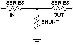
Naked VU meter should have a 3.6K series resistor. That should eliminate loading on your output, and move the normal readings up above Zero VU.
 
Thanks PRR - I was using 330 ohm for all 3 resistors.

What would you recommend for the shunt?

** Edit - from the calculator I looked at should be about 100k for the shunt resistor with 3.6k series resistors for the same sensitivity reduction (but far less loss)... let me know your thoughts.
 
Back
Top