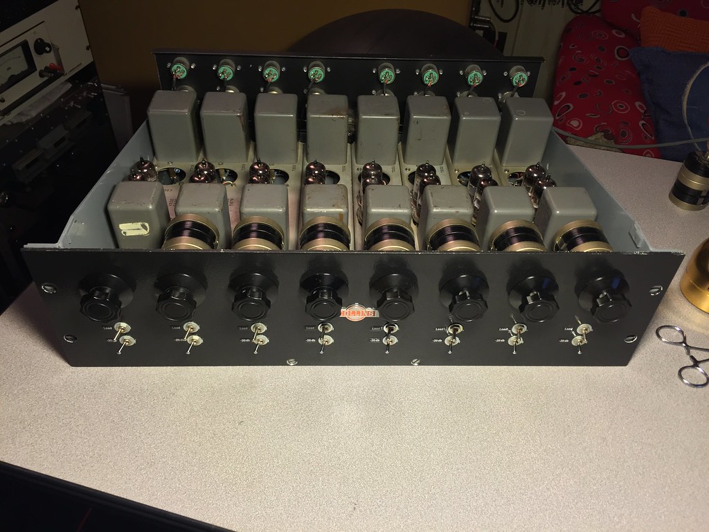
Langevin 5116 / Collins 356A Output Transformer Tertiary Feedback?

GroupDIY Audio Forum

Help Support GroupDIY Audio Forum:

This site may earn a commission from merchant affiliate links, including eBay, Amazon, and others.

Braden Sauder

New member
Joined
Oct 30, 2011
Messages
2
Hi all!

I've been wanting to build this circuit for a while now but I'm needing some info on the output transformer. I know the output transformer for the Collins 356a is 16.5k:600 and the primary is rated for 6ma unbalanced DC. The only thing i don't have any info on is the tertiary feedback winding.

just wondering if anyone has any info or any thoughts regarding the feedback winding.

I've attached the Langevin 5116 schematic.

Braden


Attachments

  • Langevin_type5116_original_version_schematic_correct.jpg
    Langevin_type5116_original_version_schematic_correct.jpg
    781 KB · Views: 109
Welcome.

Do you know the total voltage gain and the T1 ratio? Then you can figure it.
 
Braden Sauder said:
It has a fixed gain of 40db and T1 is 150/600:50K
It's very difficult to answer, because of the various possibilities regarding the impedances 6dB difference between 150 and 600r). In addition, it seems the nominal figures take into account 6dB insertion loss. Without further details, our answers could be out by up to 18dB
 
Yeah, search reveals all, yet it's hard to use here.  If you're in a sub-forum, it seems to only search that sub-forum.  I don't know of a suitable transformer available.  356A's aren't terribly expensive, unless they just spiked.  See my racked up versions documented here. 
 
I've been on the lookout for transformer options for this circuit (GE also made a similar preamp as well, the BA-1-F) for quite some time. The closest transformer I've found is the Cinemag CM-9600-T, which is a 4:1 ratio + tertiary feedback winding. The differences between that and the Langevin TF-321-B on the 5116 is nominal primary impedance (15k on the Cinemag vs 16.5k on the Langevin) and a center tap on the primary of the Cinemag. Close enough that it's probably reasonable to take a chance on. Someone mentioned a Sowter model in a previous post where we were talking about this, but the winding ratio seemed too low.

The thread linked above by moamps is probably the best for getting clues on the feedback.

Good luck. I'll be following anything you share on this.

BT
 
It's not documented as such, but there's a reference schematic based on the Ampex 351 on Cinemag's site that implies that it was designed for PP.  I asked David about it when I put in an order for different OTs a while back, and he said it'll work well in a single ended circuit. I know mileage varies w/PP OTs used that way, and so I was going to start a thread to discuss it before taking the plunge. Just had other things to finish first.
 
David should then specify the current at which it will produce full range response in a SE application.  It may not like 5-6 mA.  Tertiary will somewhat compensate, but it's not ideal and may not do the whole job.
 
I'll get with him and see what specifics I can get and post them back here.

As long as we're listing potentially sub-optimal options here, I looked through the Sowter site again and found another PP 15k:600+NFB (also intended for the Ampex 351 circuit) - the 9084. There's a single-ended model for the Ampex 350 (9915) that's also 15k:150/600 without fb. As a last resort, might ask Brian if they could add a teritary winding to that for less money than a full-on custom job.
 
Is there a reason you wouldn't buy an actual 356A?  They aren't hard to find, they aren't hard to rebuild and rack.  New transformers may cost darn near close to the cost of the real deal, then there's labor.    I know this is DIY, but I'm not certain it always should be for it's own sake.    The 9915 comes in $134 before shipping.  The plate resistance at least looks like it would work with that 6F6 transformer.  It is an enormous transformer in comparison to the original, possibly 4x the volume. 
 
Me personally? No, no reason at all why I wouldn't buy 2 - 4 356As if I came across some at a reasonable price.  I just saw the OP going down this path and want to see what can be done here as long as he's willing to plug away. If this effort fizzles like most of the others I may just be at the point of putting DIY to bed on this one. But willing to hoe in as long as someone's willing...
 
16.5 K to 600 is 27.5:1 Z,

turns is sq root = 5.244:1

NFB is probably around 10%

figure 1 turn per ohm, you got 500 turns and 50 turns for the sec,  and 2622 T for the Sec pri,

what size core?  is it a UTC?  or Langevin brand?

how many pri volts?  100?  AC flux = 100,000,000 x 100 VAC/ 4 x 20 Hz x 2600 x A(cm^2) 

B= 48,000/Area  probably 50/50 - Radiometal steel, good to 12 KG,

leave 1/2 the core for DC, we reserve 6 KG for AC,  6000 = 48,000/A ,

A=48,000/6,000 = 8 cm^2  what lam has a sq stack of 6 cm^2 ? (lets use the magic stack dims, 3 x 4)

looks like 87 EI or 100 EI, big core, probably comes in a big can,

wind like vari mu output for limited phase shift/osc

100 EI in 4%  Silicon would work, lace the core  8 x 8 for natural air gap,  good for about 250 Henries, what is the plate resistance of that tube?

original is probably 75 EI double stack, Si steel,


emrr said:
One output I checked at 120 Hz out of circuit with a hand held meter read:

16k5: 35.74h
600: 2.15h
Tert: 31mh

16k5 - 2K DCR

600 - 70R DCR

Tert - 4R DCR

Out of hundreds I've seen they are universally ADC's.  I have seen 1 example of an official UTC replacement input, which had much lower inductance than the ADC.  Can is barely smaller than UTC A size. 
 
> output transformer for the Collins 356a is 16.5k:600

Your drawing seems to show 150r output connection.

Either or both in and out may be re-tapped to give +/-6dB to 12dB different gain.

> gain of 40db and T1 is 150/600:50K

If we also assume *both* in and out are tapped to the same impedance (if we work on Power instead of voltage), then....

40dB is 1:100 of voltage in the same impedance.

600:50K is 1:9.12 gain. We need another gain of 10.95 to the 600r output tap.

Count the turns in the 600r output winding. The easiest way may be to apply 1V 1KHz to the 600 winding, wrap 10 or 100 turns around the windings, measure the voltage on this temporary winding. Work some math.

Divide by 11. Put that many turns around the core. Wire size does not matter; guitar pickup wire may be fine.

If I follow CJ's musings, we may have 500 turns on the secondary. 500/11 is 45 turns. If the winding is accessible, you should be able to hand-wind that many turns without going nuts. If it is potted and canned, you need CJ's skills.

Ideally this added winding will be "very intimate" with the secondary, a layer in the middle of the secondary layers. Just wound around the outside, it will work the same from bass to upper midrange, then lose coupling and the gain to the output winding will rise. This can probably be shimmed-out with a small cap in the interstage.
 
CJ said:
did all those 5116 circuits us NFB?  IIRC, the output was hacked, 5800 turns on a C core with thin wire that burned up, 5:1, but no NFB.

5116 is like this.  5116-B which you hacked is a completetly different PP amp. 
 
ok that makes sense as to why the 5116 core is so small,

2.15 H/ .031 H = 69.35 Z ratio so that means a 600/69=8.7  Ohm wind,

turns is root 69.35 = 8.33 : 1 , so f/b percentage is 1/8.33 =  12 percent

so if the 600 ohm wind is 500 turns, f/b turns are 500/8.33 = 60 T

inductance test could be off, so that could be 10 percent, either way, we are in the ball park.

anybody have an original they could measure the outside dims of?

 
I'm looking at 8 of them.    Loosely 1-3/4 x 1-5/8 x 2-3/8.

36436009350_092d07318e_b.jpg
 
Back
Top