Fender amp - output questions

GroupDIY Audio Forum

Help Support GroupDIY Audio Forum:

This site may earn a commission from merchant affiliate links, including eBay, Amazon, and others.

Che_Guitarra

Well-known member
Joined
Dec 22, 2012
Messages
218
Location
Australia
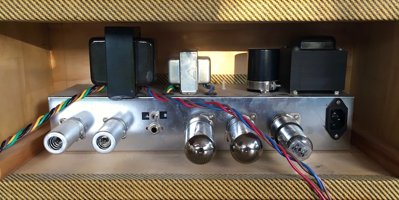
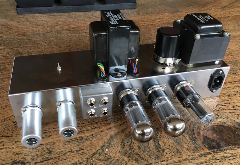
I'm about to swap the output transformer on a Fender Princeton style amp I built many years ago.  The new OT gives me the options of 4, 8, and 16 ohm taps, it has a primary impedance of 6.6K, and it's an upgrade from 15W to 20W... so my questions:

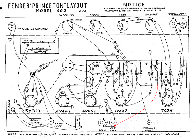
(1)  I need a three-position switch that allows me to select between each of these tap options... would that be a DP3T?  And also, switch specs are usually rated in terms of amps and volts... speakers and output transformers talk in the language of ohms and impedance... i'm not completely confident in converting this back to volts and amps...  can anyone help me translate how much switch I need?

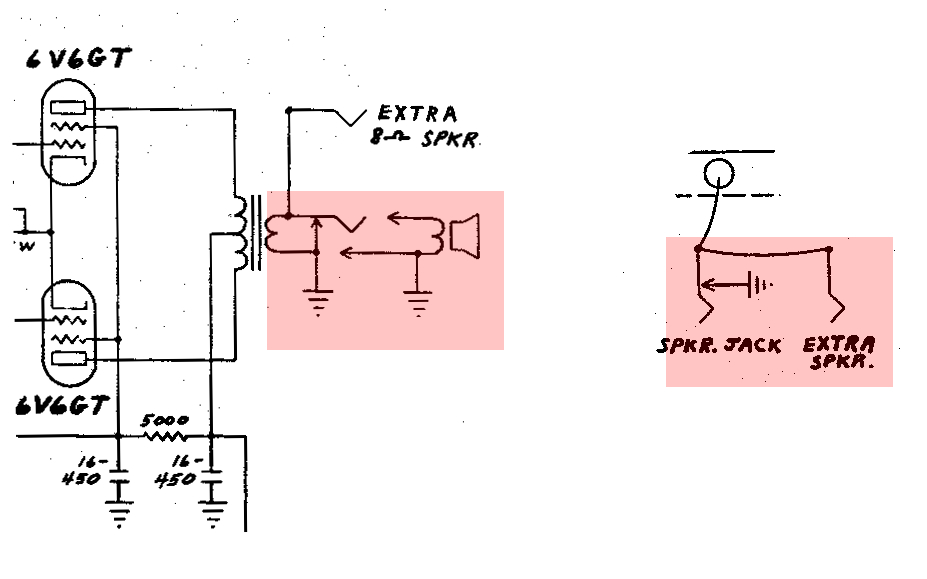
(2) I'm wanting to expand from one output jack to two, but i've got no idea how to translate these symbols.  I'm assuming the 'extra speaker' jack is just a regular mono jack, but I have no idea how to interpret that primary output jack symbol... is it a shorting jack?  Perhaps a type of jack i'm unfamiliar with?  Hmmm...

9qH3txO.jpg


I'll be much appreciative for any help you guys can give me  :)
 
Hi...

You could use a variety of switches but the simplest version is perhaps a rotary switch with three positions and 1 pole (3pos/1pol)

Usually the normal and extra outputs are connected in parallel (see attached schematic)

http://www.tubeampdoctor.com/en/shop_Switches_Optocouplers_Switches_Optocoupler/Impedance_selector_switch_used_in_TAD_Plexi_Kits_894.  (link to a good solid switch for impedance selecting)


Best regards

/John
 

Attachments

  • OT w. Switch.png
    OT w. Switch.png
    2.7 KB · Views: 9
Thanks for your reply. 

I should mention I live in Australia; most electronic stores in my area have a limited selection of switches.  Certainly nothing remotely close to the military spec quality rotary switch in the link you provided.  And from my encounters this week, I seem to know just as much about switches than most of the local electronic salespeople do... which is why I am bringing my query to a forum.

And i'm hoping to find something locally rather than spending $50 on buying a high quality switch from the USA (because that's what it ends up costing when you include postage costs to Australia... not to mention a two to three week wait for the part to arrive). 

Rotary, toggle, slider... i'm not fussed.  What I need to know in this regard, is, what current/volt capacity am I after in a switch?  I don't want to buy an under-spec switch only to fry my new output transformer at my first gig.  Nor do I want to buy a highly over-spec switch with a large footprint because I will most definitely have to modify my chassis to accomodate.

 
Hi

You are correct that you do not need that specific switch and you could use another one if you like...

The output current and voltage is unknown here but I guess it can reach 1 - 2mA and the output voltage might reach 25 - 30V p-p (Max) so many switches will do... The Alpha rotary switches (found all around the world) are rated for 300mA/ 125VDC so they will handle your OT with ease. If you use the Alpha rotary switches you will need a 3position/ 4pole (That are all 12position original but the ones with fewer positions are locked for te specific number of positions so you will get more poles with fewer positions)

Best regards

/John
 
if it is a DIY amp, then the best way to go is to add speaker jacks for 4, 8 and 16.

you could even use 2 jacks for the 4 ohm tap in case you run two 8 ohm cabs at once.

switches are ok, but a hassle to wire, kind of expensive, and if your load becomes disconnected suddenly from the OPT, you can pop the transformer, ie somebody switches the switch with a signal running thru the amp, or the switch fails altogether, that might be why a lot of Marshall's blew OPT's in the early days, that silly switch with the jumper plate,

what about having a shorting spk jack to prevent against a no load situation when the amp is running,?

just use all 2 terminal spk jacks and wire a 1K 5 watt resistor across one of the jacks.


Hi CJ

I absolutely want access to all three taps.  I have a pair of 8Ω 1x12 cabs so the 4 and 8 taps are essential, and I can foresee myself plugging into Marshall 4x12s for kicks, so access to 16Ω would also be most welcome.

As for four output jacks (2 x 4, 1 x 8, 1 x 16)... well... it could be done, but space is at an absolute premium inside the chassis.  It's a later model Princeton modded to fit inside a tweed Princeton box chassis... very tight inside. 


If I were to go this option... would I just need one of the four jacks to be a shorting plug, or would the safest design be  to make all the output jacks shorting plugs?

I'm ready to go and buy the parts now, but I might hold off for an hour or two and consider this new idea.  Hmmm.
 
you do not need a shorting jack if you do it like the pic,
but if you need space, then go for the switch,

a good Z sw will be $$$, you can order one from PV,  they will ship for free,

4 jacks from digikey, mouser, etc  will be 2 x 4 = 8 plus shipping

switchcraft  12a
 

Attachments

  • Z.png
    Z.png
    6.2 KB · Views: 4
Che_Guitarra said:
If I were to go this option... would I just need one of the four jacks to be a shorting plug, or would the safest design be  to make all the output jacks shorting plugs?
Pardon for butting in, but one switched jack, four switched jacks, neither will work. What would work, is four jacks with isolated switches all wired in series, so any jack(s) used will break the short. Cumbersome at the least, but doable.

I like CJ's 1K, 5W resistor plan for this. If CK thinks that 1K is low enough to dampen nasties, I am inclined to agree, CJ knows his stuff.

Gene

 
Basic Power, Ohms, Volts, Amps.

20 Watts in 8 Ohms is 13V and 1.6 Amps.

16 will be 1.4X more Volts, 20V. 4 Ohms will be 1.4X more Amps, 2.3 Amps.

Important distinction: a "250V 5A" switch may be expected to kill a vacuum cleaner at FULL power. On an amplifier you should be switching at NO power (at least near-silent). So while the contacts have to "hold" 2+ amps, they do not have to "break" 2+ Amps. (The 20V is nearly nothing to a switch.)

However in 3-throw switches you have the $2 switches rated 0.050A (probably not long-term adequate) and the Power switches used on commercial amps and sold in amp-supply shops ($$).

3 jacks is cheaper than a good switch. And may be smaller.

Two DP toggles can work, small/cheap, but it confuses the user.

Is a 4X10 really 16 Ohms? Is it actually four 64 Ohm speakers?

 
Before:

jsS5bQk.jpg


After:

3pjkPth.jpg


After CJ went through the effort to draw me a schematic, how could I say no to his idea?  But seriously - thanks CJ - I don't post here much, and whether you realise it or not, you always give me the best of advice.  A virtual high-five out your way, good sir  8)

Space was too tight in the chassis for any of the above suggestions, so creativity saved the day... the smallest hammond case I could find - hacksawed in half, drilled, retapped for an unseen purpose!  At the end of the day, it works quite well.

Also -  I went to the better electronics shop in my area, and all their mono jacks area shorting jacks... now i've seen a shorting jack I understand it's up to the user to employ the shorting function or not.  How does that change what I should do?  I've currently got all four jacks wired up in mono fashion.


I also need to know what to do with this part of the circuit (in red).  Do I now need to run a contact from each output tap to this location?  Or is one run from one tap (say, 8Ω) enough?

V3lbgVP.jpg
 
Just wire-up NFB to the original impedance. The others will track in correct ratio with 99.44% accuracy.
 
thanks for the props,  :D

wow, that was fast!  good job,

you know that the secondary winding of an output transformer is typically around 0.2 ohms or lower for the first tap, so if you add up your speaker wire resistance, your Z switch resistance, your phone jack  and plug resistance, it all goes into counter acting that nice big wire they use for the speaker wind,  sure, a switch will have low contact resistance when it is brand new, but after 5 or 10 years you might develop some ohmage across those contacts, with the hard wire into the phone jacks you do away with that variable, you want to control the speaker with your guitar, this means max dampening factor desirable, so the less stuff between the speak and the transformer, the better.  Hardwired combo amps like the Reverb Rocket do away with the jack and the plug which is about as good as you can do short of running the secondary wire out to the speaker,

your build looks nicer than this reverb model>

https://groupdiy.com/index.php?topic=50236.0

i use that amp for clubs because you can crank it up to 7 without the people leaving, but bass and rhythm guys on the other side of the drummer complain because they can not hear me, and we don't like to mic the amp like these modern guys with their ear buds and isolation/mic boxes, "let the PA do the work" screw that how am i gonna get my tone? don't wanna worry about uncompressed transients with the onboard jfet booster  blaring out over the PA either, so we are building a Tweed DeLuxe xfmr with a 4 ohm tap (original is just 8 only) so we can run a satellite speaker over to the other side of the stage for the bass/rhythm geeks. doing a mic to monitor thing introduces extra hassle like getting the mix right, another mic and cable to set up/pack up, and have you ever heard a guitar thru a self powered Class D monitor, yuk!

you can run 4 ohms of an 8 ohm jack but your tubes might take a beating by way of excess plate current, which can also affect tone, here is the Tweed DeLuxe coil with the 4 ohm tap, >
 

Attachments

  • tweed xfmr.JPG
    tweed xfmr.JPG
    173.1 KB · Views: 11
I must say that using different jacks are just fine and a very solid solution until you start hesitating on which one is the correct one... I guess a good marking of them all and their interaction is crucial for a long term use... long time = easy to forget or mixup, especially if you alter between different amps and speakers.

To make best use of all secondary taps all "three" of them should be parallel giving us six different jacks to alter between... especially if we have an amplifier head where it is common to alter speakers between home, rehearsal studio, studio and perhaps gigs.

That is why I prefer the switch arrangement with one "normal" jack and an "extra" i parallel... then it is easy to do the math.

Your opinion may vary though :)


Best regards

/John
 

Latest posts

Back
Top