Yamaha D1500 Audio Level Meter Malfunction

GroupDIY Audio Forum

Help Support GroupDIY Audio Forum:

This site may earn a commission from merchant affiliate links, including eBay, Amazon, and others.

lahatte

Member
Joined
Sep 16, 2017
Messages
9
Hi there. I have an issue I can't figure out. If someone could offer any advice on this that would be great.

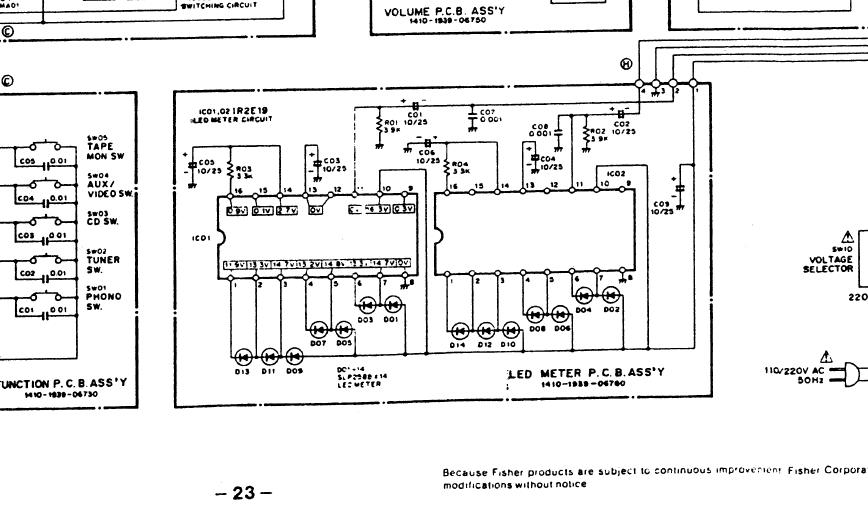
The device is a Yamaha D1500 digital delay. The service manual is attached in the next post, but no good schematics are there. I attached a diagram of the LED meter from a SPX90 that looks to be set up the same way, and uses the same driver IC (IR2E19).

The problem is some of the LEDs in the LED meter stack are not lighting properly. At this point only the top three will light with the higher audio input levels. The lower LEDs on the meter stack will not light. The two on the very bottom used to light until I did some attempts to get the middle ones to light by shorting some connections, hoping for power to them.

Anyway, I replaced the LED driver IC (a supposed substitute I could find for the IR2E19), but there was no change. I have gotten some of the other LEDs in the stack to light by accessing some voltage source, but nothing consistent, so I do not know that the LED stack itself is defective. I also tried another LED stack which didn't work at all, but then I do not know the voltage requirements for that.

The D1500 works fine other than this audio meter issue. Could there be an issue with a capacitor or something that drives the IC? I wish the schematic showed acceptable voltages for the inputs, otherwise I do not know what are good or bad voltages.

Also, it would be helpful to understand why some LED's are in series. I cannot find a datasheet for the IR2E19.

Thanks!
Clay
 

Attachments

  • Yamaha_SPX90_mono_LED_Meter_IR2E19.jpg
    Yamaha_SPX90_mono_LED_Meter_IR2E19.jpg
    72.2 KB · Views: 15
Service Manual, kinda useless for this...
 

Attachments

  • yamaha_d1500_service_manual.pdf
    1.7 MB · Views: 17
lahatte said:
Could there be an issue with a capacitor or something that drives the IC? I

Not certain but there are resistors there as well?

lahatte said:
I wish the schematic showed acceptable voltages for the inputs, otherwise I do not know what are good or bad voltages.

Kinda blurry....But this circuit has some voltages??

post-59-1352640166.jpg


lahatte said:
Also, it would be helpful to understand why some LED's are in series. I cannot find a datasheet for the IR2E19.

I attached a data sheet I've found.....

Good luck!!

I'm interested in your fix as well....BTW....What does the 7 segment LED diagnostic test show?


Attachments

  • IR2E19.pdf
    109 KB · Views: 16
Thanks for that image. It is indeed very difficult to read. I can't really make out the numbers. Do you know what Fisher product that schematic is for? Maybe there is a better version out there.

I haven't removed the LED meter stack from the little PCB, which connects some of the LEDs together, as shown in the images. I guess I'll need to do that, and try testing each LED with a voltage source.
 
Found it, and I found a better one...

And thanks for the heads up on the image with voltages. This should be helpful indeed.
 

Attachments

  • IR2E19 with Voltages, Fisher CA-270.jpg
    IR2E19 with Voltages, Fisher CA-270.jpg
    262.8 KB · Views: 14
I have pretty much determined that the 1st and 3rd LEDs are not working, and since the 2nd and 4th LEDs get their feeds through the 1st and 3rd respectively, that's why they do not light up under normal operation.

Even though the schematic shows that the power to the LEDs and IC should be 15 or 16v, I get 10v when I check my voltage source (low voltage due to power supply capacitors maybe?). The LED stack I have to for replacement apparently uses a max of 5v. So, if I put a 1K resistor (assuming 10v source) on the power feed to the LED stack I can get an LED in the stack to light by tapping that 10v source.

I will go ahead and remove the old stack and put on the new one, add the resistor to the power feed wire, and try it out.

By the way, it seems the voltages shown on the pins on the LED side of the IC are what is expected to be seen there after the power goes through the LED.
 
So I just discovered that the LED bar graph I intended to use is not the same size as the original.  8 segments on the new one fit in the space of 7 on the old one.

Anyone know how to get one that matches the original?
 

Attachments

  • 20171106_201944.jpg
    20171106_201944.jpg
    573.7 KB · Views: 8
lahatte said:
So I just discovered that the LED bar graph I intended to use is not the same size as the original.  8 segments on the new one fit in the space of 7 on the old one.

Anyone know how to get one that matches the original?

You said an SPX90 is the same????? Those are more common and probably easier to find parts for or a donor????? IDK....Is there a part number on there???? Guess you can't take it apart????
 
Well, yea, but I don't want to pay $50+ plus shipping just to get an LED meter.

I may end up having to use individual LEDs, remove the LEDs from the original package, then I can stick the individual ones in the old package.
 
lahatte said:
Well, yea, but I don't want to pay $50+ plus shipping just to get an LED meter.

I may end up having to use individual LEDs, remove the LEDs from the original package, then I can stick the individual ones in the old package.


Yeah..... I actually mentioned that(taking apart)  as you were saying this...lol
 
Well, I finally found some individual LEDs the correct size here..., but they are in the UK, and shipping is a big $10 for $2.00 in parts... Oh well....
 
lahatte said:
Well, I finally found some individual LEDs the correct size here..., but they are in the UK, and shipping is a big $10 for $2.00 in parts... Oh well....
Beats $50 for a broken SPX though I suppose....pretty neat site.....


I always just stock up on other things if I can when I'm going through Mouser because it's always like $7 for shipping because I'm too impatient for the $5 method.........
Good luck!!!
 
> 8 segments on the new one fit in the space of 7 on the old one.

So shim it out with a bit of wood or plastic. (Right? The new is "too small"?)

If it does not have to be Museum Quality restoration, that gets the gear back in the gig.
 
PRR, the LED spacing does not match the original, thus with the black outs between lights on the front panel, some will be hidden. See the picture I posted.
 
lahatte said:
PRR, the LED spacing does not match the original, thus with the black outs between lights on the front panel, some will be hidden. See the picture I posted.

Maybe he meant shim between the leds ......but you'll have an extra led lit up but hidden????? IDK
 

Latest posts

Back
Top