Virtual earth summing with transformer

GroupDIY Audio Forum

Help Support GroupDIY Audio Forum:

This site may earn a commission from merchant affiliate links, including eBay, Amazon, and others.

fripholm

Well-known member
Joined
May 26, 2013
Messages
349
Location
DE
I'm currently trying to wrap my head around different methods for analog summing and while doing that, I've found something interesting that I really hope some of you can help me understand :)

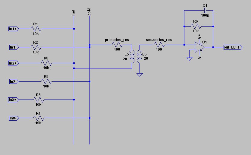
Basically, it's standard balanced virtual earth summing: There are a bunch of 10k summing resistors on a self-etched PCB with a DB25 input connector. Each channel has two resistors for HOT and COLD connected to their respective bus (HOT left, COLD left, HOT right and COLD right).

But instead of two active stages for each HOT and COLD, there's a transformer that un-balances the signal before going directly to the inverting input of an opamp. See below for a mockup. Note, that there's only one output channel shown. In reality there are two, one for LEFT and one for RIGHT. The transformers and opamps are on solderless breadboard at the moment.

VE_transformer_mockup.jpg


I didn't really expect this to work at all - but it does - and this EXTREMELY well, I might add!  ;D

Even on breadboard, the noise is vanishingly low, CMRR is very good and crosstalk between LEFT and RIGHT is less than -90dB at 1kHz. Frequency response is ruler flat up to almost 30kHz (I'm using OEP K30A06C line input transformers). I also expected to see the typical low frequency distortion of a transformer but even that is much better than I thought. Maybe because the voltage across the primary is so low. There are also no hints of instability in the output signal, as seen on the oscilloscope.

My suspicion is that it's merely current that gets transferred to the op-amp as opposed to voltage. That is also suggested by the fact that the output signal gets lower, when the transformer is configured to a voltage step-up of 1:2, which should decrease the current on the secondary. By turning the transformer around for 2:1, the output signal gets louder but at the same time the frequency response starts to decline.

When I did my research, I've never stumbled across this kind of summing stage before and I'm starting to wonder, why this is?! From the measurements I did, it works quite well and there are only two transformers in the whole circuit instead of one for each input channel.

Is there something I'm missing, any obvious or not so obvious drawbacks?


You are not actually doing virtual earth summing.  Basically it's passive summing with a makeup gain stage.  Similar to the popular resistor box feeding a mic pre configuration.
 
fripholm said:
When I did my research, I've never stumbled across this kind of summing stage before and I'm starting to wonder, why this is?! From the measurements I did, it works quite well and there are only two transformers in the whole circuit instead of one for each input channel.

Is there something I'm missing, any obvious or not so obvious drawbacks?
Maybe have a look at Neumann/Filtek/TAB/Lawo/Siemens/Telefunken Vx75 for the busamp 'Sammelschienenverstärker' ...
Substitute 'x' by 2, 3, 4, 6, 9, depending on manufacturer, fi. V475 for Neumann, to sum up to 100 inputs or up to 2 x 100 inputs for the Vx75-2 dual (l/r) version ...
 
I am ot sure this is actually operating as a VE mixer. The datasheet for the OEP K30A06C list the primary and secondary dcr as close to 1000 ohms. Also the inductances are around 120H - both of whih are different to your schematic.

The op amp creates a VE at its -ve terminal so the transformer secondary is effectively shorted, The primary dcr is therefore reflected to the secondary and will appear in series with the primary dcr  so the input to the transformer 'looks like' 2K. The pair of 10K input resistors forms a roughly 10:1 pot divider with this 2K.

In the secondary side the op amp gain is effectively the 1K secondary dcr divided into the 10K feedback resistor - so it is about 10 which compensates almost exactly for the loss on the primary.

This analysis ma or may not be correct. The acid test is the interaction of inputs, If it is acting as a VE summer then there will be no difference in gain on a channel between the case where all the other input channels are shorted and the case where they are all open. If there is a difference then it is more likely regular voltage summing.

Cheers

Ian
 
john12ax7 said:
Basically it's passive summing with a makeup gain stage.  Similar to the popular resistor box feeding a mic pre configuration.

But wouldn't that have a non-inverting opamp at the secondary? Like an API style mic pre? In this case the transformer is feeding the inverting input...

Harpo said:
Maybe have a look at Neumann/Filtek/TAB/Lawo/Siemens/Telefunken Vx75 for the busamp 'Sammelschienenverstärker' ...

Ohh, nice find, thanks! They are very similar, except that the non-inverting input is not at ground but at the half of the unipolar supply rail.

So, what exactly is that? Some kind of mixture between voltage (passive) and current (VE) summing?! If Neumann used this in their consoles, the drawbacks might not be that big of a deal...  ???
 
ruffrecords said:
I am ot sure this is actually operating as a VE mixer. The datasheet for the OEP K30A06C list the primary and secondary dcr as close to 1000 ohms. Also the inductances are around 120H - both of whih are different to your schematic.

As I said, it was just a quick mockup to show the basic circuit. But you are right, I could have been more precise with the values.

This analysis ma or may not be correct. The acid test is the interaction of inputs, If it is acting as a VE summer then there will be no difference in gain on a channel between the case where all the other input channels are shorted and the case where they are all open. If there is a difference then it is more likely regular voltage summing.

There is a difference - but it's with regards to crosstalk. On the self-etched board there are four additional inputs (one stereo and two mono, each on TRS) besides the DB25 connector. When they are open (not terminated), the crosstalk between L and R is just -30dB. When they are connected (terminated), it's -90dB as mentioned.

As far as I remember, the output level didn't change when these are terminated vs. open. Currently, I don't have it in front of me. Need to check again this evening.

Thanks a lot so far.
 
fripholm said:
As I said, it was just a quick mockup to show the basic circuit. But you are right, I could have been more precise with the values.

There is a difference - but it's with regards to crosstalk. On the self-etched board there are four additional inputs (one stereo and two mono, each on TRS) besides the DB25 connector. When they are open (not terminated), the crosstalk between L and R is just -30dB. When they are connected (terminated), it's -90dB as mentioned.

As far as I remember, the output level didn't change when these are terminated vs. open. Currently, I don't have it in front of me. Need to check again this evening.

Thanks a lot so far.

If the crosstalk changes that much then it is definitely regular voltage summing. I didn't know you had any mono inputs which is why I suggested the level check. But crosstalk is a much more sensitive measure of the type of summing. With VE summing the crosstalk should not change. The reason it changes with voltage summing when you disconnect inputs is that the bus impedance rises so the attenuation from an input to the bus is less. How many inputs do you have at the moment?

You might get a lot closer to VE summing (via a transformer) if you changed the transformer for a 600:600 type.

Cheers

Ian
 
Ignoring the source impedance of the transformer the inverting stage has a gain of 10k/400

Noise performance is good compared to what?

If you have a scope or VOM, inject a sine wave into one input and measure voltage at primary and secondary of transformer.  That should reveal what is going on.

I am not sure I see any benefit there other than single ending the differential buses, but op amps are cheaper (and better) than transformers these days.

JR
 
JohnRoberts said:
Ignoring the source impedance of the transformer the inverting stage has a gain of 10k/400

Noise performance is good compared to what?

If you have a scope or VOM, inject a sine wave into one input and measure voltage at primary and secondary of transformer.  That should reveal what is going on.

I am not sure I see any benefit there other than single ending the differential buses, but op amps are cheaper (and better) than transformers these days.

JR

No argument that for accuracy opamp 'analogue computation' is the way to go as in other areas of instrumentation - the electrons and holes don't 'know' they are audio  ;)
Passive summing seems a poor solution from a technical point of view - impedances / make up gain etc.

But if people like the 'sound' - real or perceived - of something they'll go for it I guess...
 
Newmarket said:
No argument that for accuracy opamp 'analogue computation' is the way to go as in other areas of instrumentation - the electrons and holes don't 'know' they are audio  ;)
Passive summing seems a poor solution from a technical point of view - impedances / make up gain etc.
Passive summing is not as much of a compromise as people surmise. The noise gain of a virtual earth summer**** will be similar to the makeup gain of a passive summer for same number of inputs  so six of one half dozen other.
But if people like the 'sound' - real or perceived - of something they'll go for it I guess...
ding ding ding... the secret sauce for passive summing is that people use their favorite "colorful" makeup gain stage, so it adds a specific sound signature having little to do with the summing technique.

JR

**** Back in the day i substituted current sources for resistors in a VE summer and reduced that noise gain significantly but Yawn.... digital summing is arbitrarily perfect so why bother.  ::)
 
Newmarket said:
No argument that for accuracy opamp 'analogue computation' is the way to go as in other areas of instrumentation - the electrons and holes don't 'know' they are audio  ;)
Passive summing seems a poor solution from a technical point of view - impedances / make up gain etc.

Theoretically, the two techniques are almost identical. In practice, both have limitations. Passive summing requires unused sends are connected to 0V to maintain bus impedance (and hence gain and crosstalk figures). Large numbers of channels connected to a virtual earth can cause serious instability. In noise terms there is nothing to choose between them.

Cheeers

Ian
 
JohnRoberts said:
**** Back in the day i substituted current sources for resistors in a VE summer and reduced that noise gain significantly but Yawn.... digital summing is arbitrarily perfect so why bother.  ::)

If you have access to it, have a look at the EMI TG12345 console schematics.  Mike Bachelor used an E-to-I stage (Amplifier type B) as the mix bus interface.  The mix bus itself consisted of a single unscreened wire for each group down the wiring loom.

Neat peice of kit.

Regards

Mike
 
fripholm said:
But wouldn't that have a non-inverting opamp at the secondary? Like an API style mic pre? In this case the transformer is feeding the inverting input...

In that specific case yes.  So it's not exact but still similar. Whether it's non- inverting or inverting they are both voltage gain stages.
 
madswitcher said:
If you have access to it, have a look at the EMI TG12345 console schematics.
I don't
Mike Bachelor used an E-to-I stage (Amplifier type B) as the mix bus interface.
not sure what amplifier type B means
The mix bus itself consisted of a single unscreened wire for each group down the wiring loom.

Neat peice of kit.

Regards

Mike
I described current source summing in my console design article published in 1980... At least one console designer shared with me that he used the technique after reading about it, (in a broadcast console he designed).

Most people just didn't believe it could work.  ;D ;D

JR
 
JohnRoberts said:
Most people just didn't believe it could work.  ;D ;D

Was this a reluctance specific to audio folks?  Current summing through a transimpedance amplifier is a common thing for a variety of EE fields,  though I'm not sure when it became common.
 
john12ax7 said:
Was this a reluctance specific to audio folks?  Current summing through a transimpedance amplifier is a common thing for a variety of EE fields,  though I'm not sure when it became common.
I am not sure we are on the same page...  I had this problem back in the 70's trying to explain my invention to the patent office.

The wet behind the ears patent examiner couldn't see the difference between summing "currents" into the - input of an inverting amplifier (that the textbooks all describe as "summing currents") , and the current sources of my invention that have a very high output impedance and compliant current output.  Of course the op amp notices the difference because the high impedance current sources do not increase the sum amp's noise gain like summing resistors connected to low Z voltage sources do.

At the time I did not have the cash to complete the patent examiner's insufficient education, so abandoned my application. My patent lawyer would have happily kept burning my dollars.  Me not so happy.


JR
 
fripholm said:
So, what exactly is that? Some kind of mixture between voltage (passive) and current (VE) summing?! If Neumann used this in their consoles, the drawbacks might not be that big of a deal...  ???
It is zero ohm summing (0-Ohm-Knotenpunkttechnik).
Discussed here:
https://groupdiy.com/index.php?topic=5253.0

By one of those cards and you are done.
https://groupdiy.com/index.php?topic=13857.0
 
transformers will make anything better, bake a chocolate cake with an API  2503 inside and tell me it don't taste better, stick a Peerless K-241-D in your air cleaner and tell me you don't get better mileage, put a UTC A-10 under the Christmas tree and tell me it don't smell better,  jus sayin, wtf, over?
 
john12ax7 said:
You are not actually doing virtual earth summing.  Basically it's passive summing with a makeup gain stage. 
I beg to disagree. Because of parasitics this is no perfect "zero-ohm" VE but still, the fact that the very low impedance of the node is created by NFB and the current-to-voltage conversion actually do qualify for VE.
The big disadvantage with the use of a transformer in this arrangement is that the current flow through the xfmr to the "ground" reference; this current is a source of x-talk. In a true VE, the current flows ultimately through the supply rails, and since the reference is not submitted to this current, it does not contribute to X-talk.
There are advantages, such as elimination of one source of longitudinal noise (between reference bus and summing-amp refrence point) and possible noise optimization of the source impedance seen by the opamp.
 

Latest posts

Back
Top