Long skinny channel strips

GroupDIY Audio Forum

Help Support GroupDIY Audio Forum:

This site may earn a commission from merchant affiliate links, including eBay, Amazon, and others.

ruffrecords

Well-known member
Joined
Nov 10, 2006
Messages
16,235
Location
Norfolk - UK
A few months ago I bought some EELA consoles with a view to turning them into tube consoles. The main channel strip in these is 40mm wide and 375mm long. It is made from a single piece of U shaped steel which gives it the necessary strength over the 375mm unsupported span. I don't have the money to have a custom steel U shape made for my own strips so I am looking at alternative more flexible schemes. And I am wondering if the basic scheme I now use for my Mark 3 tube modules micgh still work over this span. It works like this:

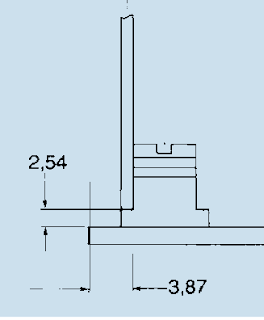
The front panel is 2mm aluminium and is mostly cosmetic. The PCB would run all along the left edge of the front panel, connected to it at intervals by a standard die casting. Along the right edge would run a steel sheet basically the same size as the PCB and also attached to the front panel by die castings. The modules would be about 75mm deep so both the PCB and the steel sheet would be this deep. Together with the front panel they form a 75 by 40 by 75 U shape. In the Mark 3 I turn this into a rigid box by  tying the back of the PCB and steel sheet together using metal pillars placed on the same spacing as the die casings. Here is a pic of how this works in a normal (short) modules:

7HPlashup.png


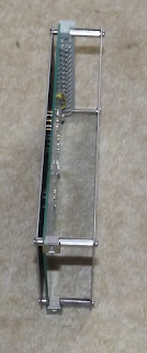
It works fine over the 128mm length of my normal modules if I space the supporting pillars and die castings at this sort of interval I am hoping it will be as strong. My only other concern is that the front panel extends about 5mm at the top and bottom in order to attach the modules to the frame. This 5mm of aluminium top and bottom easily supports a 128mm high module but will it be OK for 375mm?? Most of the weight of the module would be in the steel supporting sheet.

Looking for a sanity check please.

Cheers

Ian
 
Why don't you use an L-shaped extrusion? Standard size 40x20x2.
That's what I used when I made mixers. Never had any issue with modules up to 600mm long.
Note that the alloy used for extrusions is generally more robust (stiffer) than that used for flat sheets.
How are you drilling/milling the fascias? DIY or subcontract?
 
abbey road d enfer said:
Why don't you use an L-shaped extrusion? Standard size 40x20x2.
That's what I used when I made mixers. Never had any issue with modules up to 600mm long.
Note that the alloy used for extrusions is generally more robust (stiffer) than that used for flat sheets.
How are you drilling/milling the fascias? DIY or subcontract?

How do you do the interface to the frame with an L shaped extrusion?

Also, can't seem to find any except in China.


Cheers

Ian
 
ruffrecords said:
How do you do the interface to the frame with an L shaped extrusion?
I used different techniques. At first, I used 10x5mm extrusions bolted to the small side (vertical) of the L and fixed the PCB to the extrusions. Later, I used the pot shafts to affix the PCB to the extrusion, with the occasional reinforcement of a threaded dice.

Also, can't seem to find any except in China.
This company will cut at length in any quantity.
http://www.metalaladecoupe.com/francais/cornieres_ailes_inegales1.asp?tbout=alu
 
You can make an extrusion in any shape you want, but must take a bunch of it , which makes it ineffective for one offs. There are lots of stock extrusion shapes in the market.

A console I did the electronics for back in the late 70's/early 80s used an I shaped extrusion for the channel stips, with a slide in sheet metal faceplate fascia. The nice thing about it was consistent width... load up a frame with bent channel metal can be fun and games due to tolerance.

I surely wouldn't do it that way now, too many secondary operations.

Maybe research more standard extrusions, there are a lot out there.

JR
 
If you used an extrusion with a lip either side, as JR suggests, you could use a strip of Traffolyte for the top surface and engrave it as required

It would look wonderfully old-school

Nick Froome
 
OK, thanks for the inputs. Clearly extrusion is an option but.... I have a module system that works. If can just extend it for use also for long modules that would be preferable - I am sure you will understand I don't really want to do a complete mechanical redesign if I don't have to. So, back to the original question, do you think what I have will work.

Cheers

Ian
 
ruffrecords said:
This 5mm of aluminium top and bottom easily supports a 128mm high module but will it be OK for 375mm?? Most of the weight of the module would be in the steel supporting sheet.

If your 375mm high is enough rigid I don't see how 5mm support will fail, even 1mm will do the job.
The critical "bending point" will be between the rail support edge and first die casing, not really mater how far you extend at rail side
It's how I visualize physics here, if i'm not wrong...
Of course having room for the screw to rail is needed, M2.5 I guess for euro rack, your 5mm should be fine.

Best
Zam
 
zamproject said:
If your 375mm high is enough rigid I don't see how 5mm support will fail, even 1mm will do the job.
The critical "bending point" will be between the rail support edge and first die casing, not really mater how far you extend at rail side
It's how I visualize physics here, if i'm not wrong...
Of course having room for the screw to rail is needed, M2.5 I guess for euro rack, your 5mm should be fine.

Best
Zam

The only thing I was thinking was if the whole 375mm was unsupported then the bending moment at the support would be much greater than  for a 128mm module. But. if I brace the 375mm every 128mm then it should be the same (it is a loooong time since I did' A' level Applied maths).

I think what I will do is make a mock up. I already have a source for the steel  and aluminium that will cut to size. I'll let you know how I get on.

Cheers

Ian
 
ruffrecords said:
The only thing I was thinking was if the whole 375mm was unsupported then the bending moment at the support would be much greater than  for a 128mm module.

That's for sure, and with 2mm alu, the middle will bend forever if you push to much...
Also don't underestimate all the pot an switches holes that will weaken the front panel

ruffrecords said:
But. if I brace the 375mm every 128mm then it should be the same (it is a loooong time since I did' A' level Applied maths).

I think you can't extrapolate this way, for few reasons.
-your brace are not continuous all long (like a L or U shape), also don't know if pcb touch the front panel to help rigidity, if you have a little room each point will act like a hinge
-your brace is only at one side of the front panel, so will bend unequal at right and left hand

ruffrecords said:
I think what I will do is make a mock up. I already have a source for the steel  and aluminium that will cut to size. I'll let you know how I get on.

Possibly the best crash test!

What about replacing those eurocard bracket by a long smal L profile , it won't change your global mechanical design
You can have it fixed with 3 or 4 screw for proper alignment BUT glued with industrial bicomposent araldit (it work well!)
You can also have a "standard" front panel with all holes options, and a second one 1/2mm for cosmetic and label...
advantage... no visible screw  8)

Best
Zam
 
Thanks for the input Zam.

I think the bracing is continuous - it is just attached to the front panel at discrete points. Also my brace is on both sides of the panel. On one side its the PCB, on the other it is a steel sheet (screen).

A long small L profile is an interesting thought.

But you are right, building one is the only way to be sure. Metal bits should be here on Wednesday. I got the metal parts of a 6U module version the other day (266mm) so I could try that out tomorrow with an old EZTubeMixer front panel I have.

Cheers

Ian
 
Just like melting solder is the final test for circuit design, bending metal proves (or not) mechanical designs.

CAD programs are great for fit and clearances, strength not so much (at least not the cad I used).

Good Luck

JR
 
I built the 6U version of my3U scheme today. Using the die casting just at the top and bottom as in the 3U unit, you could flex the front panel by pressing on its centre. adding an extra die casting at the mid ppoint prevented this and the overall structure was then just as rigid as the 3U. The 3U die casting are on 110mm centres so it looks like this scheme will work for any length as long as there is a die casting every 110mm. Metal parts to build a 375mm version arrive on Wednesday.

If that works, who knows how log they could be made.

I may be able to get hold of a Soundcraft 500 frame. This looks to have even longer modules but I cannot find any dimensions on the net. Anyone know the dimensions of the modules in this console?

Cheers

Ian
 
I believe they're 18.5 inches, whatever that is in cm including the fader which is all one piece - I suppose you could make the fader section one separate piece for all the faders ala neve/ssl

Edit

The 500 is the same frame as the 6000 and practically the same desk

https://3e7777c294b9bcaa5486-bc95634e606bab3d0a267a5a7901c44d.ssl.cf2.rackcdn.com/product_documents/documents/5098_1478538863/Soundcraft6000UG_original.pdf
 
Timjag said:
I believe they're 18.5 inches, whatever that is in cm including the fader which is all one piece - I suppose you could make the fader section one separate piece for all the faders ala neve/ssl

Edit

The 500 is the same frame as the 6000 and practically the same desk

https://3e7777c294b9bcaa5486-bc95634e606bab3d0a267a5a7901c44d.ssl.cf2.rackcdn.com/product_documents/documents/5098_1478538863/Soundcraft6000UG_original.pdf

Thanks for the info. 18.5 inches is just under 470mm so it is easily the longest I have considered.

Cheers

Ian
 
ruffrecords said:
The 3U die casting are on 110mm centres
Ian, from thebeginning of this thread, I've been wondering what is a "die casting"... Actually, I know what die-cast means, but here you use the term for something specific - I guess it's the threaded parts that allow right-angle connection, but I would like to know if it's the sanctified term for this kind of part and where you found these, just out of curiosity.
 
abbey road d enfer said:
Ian, from thebeginning of this thread, I've been wondering what is a "die casting"... Actually, I know what die-cast means, but here you use the term for something specific - I guess it's the threaded parts that allow right-angle connection, but I would like to know if it's the sanctified term for this kind of part and where you found these, just out of curiosity.

Here you go Abbey:

http://uk.farnell.com/schroff/60807-181/bracket-to-fix-pcb-to-panel/dp/2292872

and here is a sketch of how they are used:

PCBheight.png


This is a plan view of a corner of a module. The vertical part is the PCB and the horizontal part is the front panel.


Cheers

Ian
 
ruffrecords said:
Here you go Abbey:

This is a plan view of a corner of a module. The vertical part is the PCB and the horizontal part is the front panel.
Thanks for the info, Ian. They are bloody expensive, methinks.
I had similar things subcontracted from my metalworker, the cost was a fraction of that.
Similar to these, in fact:
http://uk.farnell.com/ettinger/05-60-223/cube-standoff-threaded-m2-5m3/dp/1466865?MER=bn_level5_5NP_EngagementRecSingleItem_3
Wouldn't they be suitable?

I still believe the L-shaped extrusion option is much more cost effective. I understand your reasons for continuing with a proven solution, but still I think there's room for improvement in the costing of the finished product, even for small production runs.
 
abbey road d enfer said:
Thanks for the info, Ian. They are bloody expensive, methinks.

Indeed they are and a little while back I had a thread here on that very topic. In the end I found a local supplier (SRS) who charged just 99 pence each. A lot of DIN Eurorack parts seems to have increased a lot in price recently (those die castings used to be half that price at Farnell). I was previously using extruded cassettes by Fischer. Screening is 100%, mechanical rigidity is first class but the price had risen by over 50% so for some time I have been examining lower cost alternatives as described here in my blog:

https://mark3vtm.blogspot.co.uk/2017/12/fat-ones-thin-ones-tall-ones-short-ones.html

I also looked at the Farnell alternatives. Unfortunately the Eurocard spec requires a 2.54mm gap between the edge of the PCB and the front panel - I have no idea why. So I could not get the Farnell parts to work and meet that spec. I suppose I could make all my PCBs 2.54mm longer.

However, I just realised the PCBs for the long skinny modules don't fit into a rack so they do not have to meet the DIN standard so there is no reason not to use the cheaper Farnell part. Thanks Abbey for helping me get my thoughts in order.

Cheers

Ian
 
The parts for building a prototype long skinny module arrived yesterday. Here are some pics of it. First the completed module from the front:

betterfront.jpg


You can see I have connected it to the sides at four points. There is a larger distance between the bottom two because that is where the fader would normally be.  I placed the holes very roughly by eye. I drilled the two side sheets clamped together so they would line up. I then used one as a template for the the holes in the front panel. The front panel is 2mm aluminium. The sides are of 1mm cold rolled steel. Next the back of the module:

back.jpg


You can see the small threaded blocks that connect the front panel to the steel sides. The back of the module is just held together with regular standoffs (I did not have any the right size so I had to improvise).

You can see the construction a little better with one side removed:

sideoff.jpg


Here is the rear of the front panel with the standoffs fitted. They are attached to the front panel using M2.5 screws. They have an M3 thread at right angles which is used to attach the side. In the real thing only one side will be a steel screen; the other will be a PCB.

frontpanel.jpg


Lastly here is a close up of the front panel fixings blocks:

standoffscloseup.jpg


The completed unit is very strong - I can stand on it without it suffering any ill effects. The strength comes mainly from the two side panels butting directly against the aluminium front panel. I then tried it in the EELA frame. It fits well but the limitations of the aluminium panel are apparent. I should have placed the very top and bottom fixings as close to the end of the front panel as possible because the aluminium from there on interfaces with the frame and takes the module weight plus that of any idiot sticking his big boot on it (me). It is most noticeable at the fader end where the last fixing is 20mm from the end of the front panel. Applying modest pressure with my boot I could bend the aluminium. At the top, where the gap is only 12mm there is no visible bending. I need to move the top and bottom fixings to their final positions 5mm from the edge of the aluminium and repeat this test to be certain this will work. The results so far are encouraging.

Cheers

Ian
 

Latest posts

Back
Top