HPF circuit's slippery slope

GroupDIY Audio Forum

Help Support GroupDIY Audio Forum:

This site may earn a commission from merchant affiliate links, including eBay, Amazon, and others.

boji

Well-known member
Joined
Jan 6, 2010
Messages
2,377
Location
Maryland, USA
I can't seem to get the right figures when I try to calculate the cutoff frequency of caps...
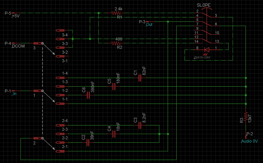
By nature of the circuit I reviewed, Jumping pins 2+3 ought to give -6db,  jumping 1+2, roughly -12db. 

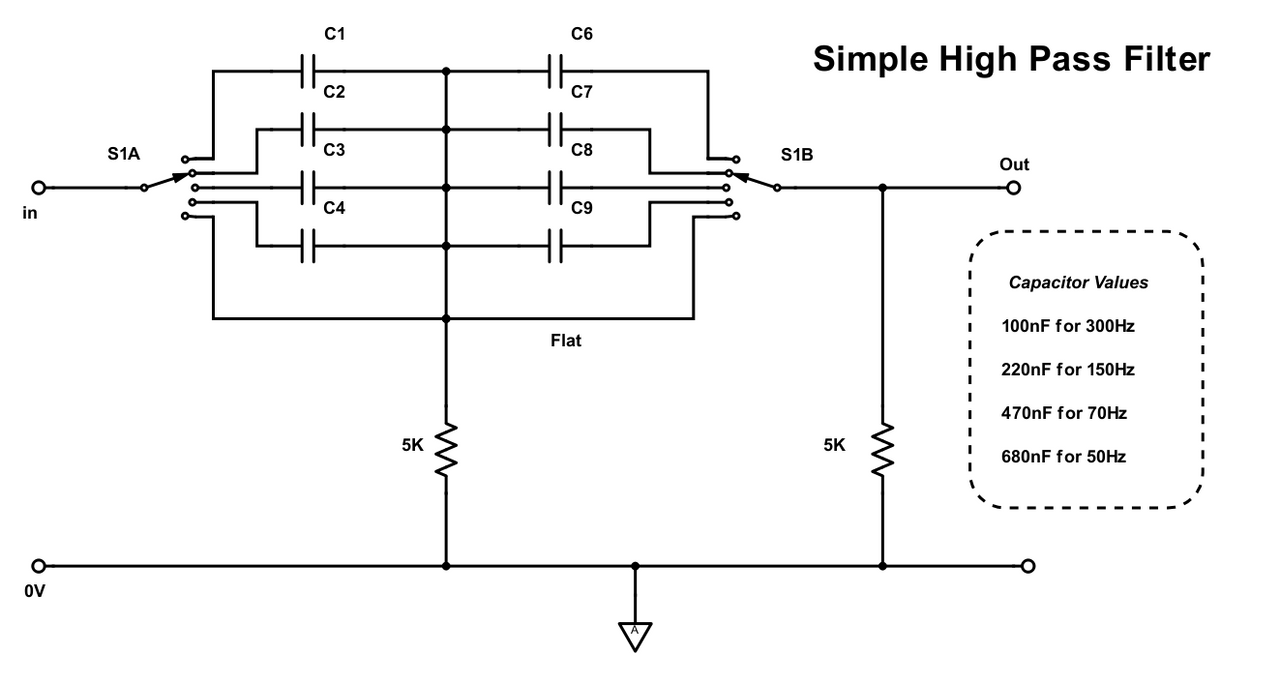
My limited understanding is putting caps in parallel raises the overall value (lowering the cutoff), but in this circuit the caps go in series?!?
I must either be missing something about how to calculate slope or more likely I have made a mistake in making or interpreting the circuit...

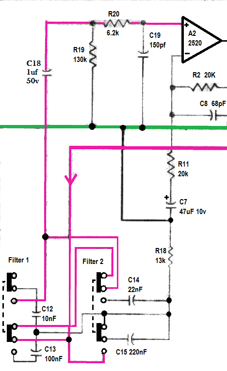
Edit: I think the second resistor (to complete the 2nd order filter) might be in front of the OpAmp, as this circuit generally seems the same as the API 536 HPF, yet with different cap values. If this is true, then my -6db/-12db annotation is reversed (Edit: Fixed for posterity's sake)...

Thanks for taking a look. And thanks for any suggestions!

in7aNs8.png


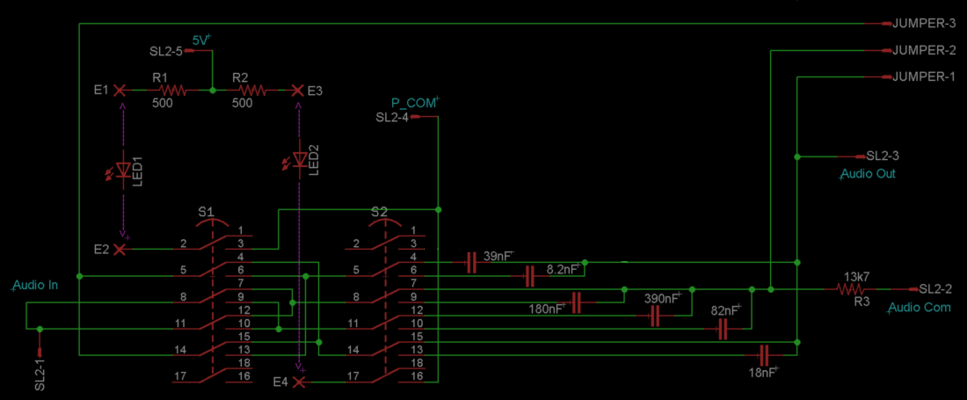
Expected frequencies:
~40Hz        390nF                        -6dB rolloff
~40Hz        390nF  +  39nF    -12dB rolloff
~80Hz        180nF                        -6dB
~80Hz        180nf  +    18nf      -12dB
~120Hz    82nf                            -6dB
~120Hz    82nf      +    8.2nf    -12dB
 
I don't see any active devices in your schematic so I am guessing it is a passive HPF. Here is my version of a simple HPF:

HPF.png


It has two stages, each of which consists of a series capacitor followed by a resistor to 0V. Each stages produces an ultimate slop of 6dB /octave so the two in series give 12dB/ocatave. Assuming the source impedance is very low and the load impedance is relatively high , then the turnover frequency is given by :

1/(2*pi*R*C)

Because the second stage follows the first without any buffering, the above assumption are not quite true. The result is that if both RCs are identical you do not get coincident turnover frequencies  but instead they are slightly separate. The ultimate slope is still 12dB/octave. In practice it works fine.

You can have a flat postion as shown by having short circuits instead of caps. You can have a 6dB/ octave position by having a short on just one of the two poles of the switch.

Cheers

Ian
 
Hey Ian

Any chance for a Poor mans HPF , PMHPF boards? that would be great
It's the filter that i use most and not so many kits.
thanks
 
Thanks RR!  Your diagram looks not unlike the circuit I posted but much easier to sort out.  You have me thinking about a rotary / push button combo instead of two pushbuttons. Btw after reviewing the API shema, after the second cap in the filter, I only see a 130k going to gnd. Is that part of the 2nd order?

QayMhLK.png
 
boji said:
Thanks RR!  Your diagram looks not unlike the circuit I posted but much easier to sort out.  You have me thinking about a rotary / push button combo instead of two pushbuttons. Btw after reviewing the API shema, after the second cap in the filter, I only see a 130k going to gnd. Is that part of the 2nd order?

QayMhLK.png

I think it is. Remember the bit I said about using two idential RC in series shifting the turnovers. I think the schematic you posted attempts to overcome this by making the R in the second filter 10 times the value of the first. So the first filter seems to have and R of 13K and a C of 200nF. The second has an R of 130K and a C of 10nF. Notice that the product of R times C is the same in both cases. Filter 2 uses different C values  for different frequencies but works in the same way. When you engage bot I guess the caps are paralleled to get a third frequency.

My design does indeed use a 2 pole rotary switch,. This is the basic design of the HPF I put in the very first tube mixer I sold.

Cheers

ian
 
guze said:
Hey Ian

Any chance for a Poor mans HPF , PMHPF boards? that would be great
It's the filter that i use most and not so many kits.
thanks

I could do but it is very easy to wire by hand. This is exactly what I did in the first mixer I built using this design. Just a regular 2 pole 6 way Lorlin switch with the parts wired on the back.

Cheers

Ian
 
"{API Skiz] makes the R in the second filter 10 times the value of the first."
Cool! Learning is fun, thank you!

Edit: By the way in your PM HPF, when caps are bypassed, why do we want to keep the two 5k resistors in circuit? Would we get a pop if they became included when selecting for HP? (Too busy to test it today)
 
boji said:
"{API Skiz] makes the R in the second filter 10 times the value of the first."
Cool! Learning is fun, thank you!

Edit: By the way in your PM HPF, when caps are bypassed, why do we want to keep the two 5k resistors in circuit? Would we get a pop if they became included when selecting for HP? (Too busy to test it today)

You don't particularly want them in circuit. It is just an added complication to switch them out. You just have to remember when calculating the C for the 6dB/octave case, the R is half what it is for the 12dB/octave case. If you use the API technique of making the second R 10 times the first R then switching  out the second R doesn't do much anyway. But you do need to make sure the input impedance of the amp following the filter is high enough not to load the second R.

Cheers

Ian
 
So I scored fifty Alco 3 pole 4 position rotary switches from  evilbay.  Size is not quite as small as grayhill mini's but for $2 each, I won't complain! Anyone have any history with this brand?

NDMNZoN.png


I'm thinking 1st position is null (off), while 3rd pole breaks led power to 6/12dB pushbutton switch.
Bipolar led illuminates slope selection.

Only alternatives that come to mind is using 3rd pole for added slope (if that's even possible).

You're more than welcome to suggest a different way to use em' in an hpf!

-Boji
 
I've been reading a bit on eq's and I had a basic question about phase.  In simple passive HP/LP filters, I see the waveform of the passed signal gets shifted forward in time. When a digital plugin eq is said to be a linear phase eq, is this because it is automatically compensating for these latency effects by shifting the entire project's latency to match the eq phase shifts? Does this have anything to do with why some analog eq's are said to sound 'musical'?

Any suggestions for reading material on the matter would be appreciated. Thank you!

Edit: I see now there's plenty on youtube about linear phase. Much to learn!
 
Phase and time are related by frequency.

A 180 degree phase whift at any frequency is half a cycle.

180 degree shift at 1KHz is 0.5mS

180 degree shift at 10KHz is 0.05mS

If we want a filter that maintains the phase relationship of the input signal, we need to make all these times identical. This means the phase shift either needs to be zero or at higher frequencies has to be be greater than at lower frequencies in order to keep these times the same. The phase therefore must increase linearly with frequency in order to do this. That is the meaning of linear phase.

That is, the phase at 2KHz must be twice that at 1KHz. The phase at 20KHz must be 20 times the phase at 1KHz. All frequencies are delayed by the same amount; this delay is called the group delay.

Almost all analogue filters do not exhibit linear phase. The simple 6dB/octave HPF for instance has zero degrees phase shift over most of the spectrum but the phase shifts to 45 degrees at the turnover frequency and then tends to 90 degrees as the frequency gets lower.

In the digital domain you can do just about anything, including the same group delay at all frequencies.

Cheers

Ian
 
Thank you Ian for your explanation!  Below is the revised skiz, accommodating the 3 pole rotary.

Abby, if you're out there, I've heard you say this is not the best design for a passive hpf.  Would something active make better sense to you?

ltzcYQH.png


Proto done, working as intended.  Thanks Ian for the inspiration assist!  Back to painstakingly wiring up these rotarys...

fEkT1nR.jpg
 
> I don't envy you connecting wires to those tiny Alco's.

Here's how Ampex did it.....  (not quite as tiny)
 

Attachments

  • Ampex-nipple.gif
    Ampex-nipple.gif
    179.2 KB · Views: 50
boji said:
Abby, if you're out there, I've heard you say this is not the best design for a passive hpf.  Would something active make better sense to you?
I wouldn't start a debate on this.
I am not an advocate of "less is best"; I think it takes what it takes to make things work.
The passive filter in API is such because their DOA's are bulky and very expensive. The drawback of passive RC filters is that they don't allow achieving the sharp response associated with RLC or active filters. Typically a Butterworth filter has 3dB attenuation at turnover frequency, when a 2nd-orderpassive RC has 6dB attenuation in the best case.
Does it matter? It's up to you. Does achieving a sharp cut-off matters? It depends. In fact, in many cases, the HP filter is used to compensate for the proximity effect of cardioid microphones, then a 1st-order filter is best. But when the HP filter is used to get rid of VLF noise, a sharp cut-off is best. In fact using a higher-order topology is recommended.
My opinion is that going active opens up the possibilities; it allows choosing perfect B'worth response (maximally flat), Chebyschev (sharper cut-off), Bessel (better phase response). Now I know that some are worried at the idea of signal going through one more active device, but IMO it's irrelevant as long as this additional device does not objectively degrades the performance.
 

Latest posts

Back
Top