Altec 1566a mods advices

GroupDIY Audio Forum

Help Support GroupDIY Audio Forum:

This site may earn a commission from merchant affiliate links, including eBay, Amazon, and others.

diggy fresh

Well-known member
Joined
Mar 19, 2014
Messages
107
Location
Montreal, Canada
Hi,  i'm soon going to try to revive an old Altec 1566a i had laying around, beat up, cut power cord etc.

I'm thinking about the basic mods floating around the net. I'm planing to use it as a high impedance preamp/di. I only have the output transformer (15095).

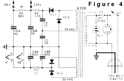
i'm planning to recap it all and change the selenium rectifier for sf4007, pretty much rebuild the power supply totaly.

Here's the schem of the power supply:
power_2b.jpg


Should i try to build a better power supply while at it? 

I know replacing the selenium rectifier by silicon diodes will give me more voltage a bit, i'm guessing the 12ax7's can take it, but should i tweak the resistors in the heater circuit?  I would try dc heater but i'm not sure i'll have enough overhead voltage.


Please let me know your experience with this preamp if you did any mods/ improvment.  I'm trying to learn about tubes.

Thanks.
John
 
>   I would try dc heater

?? It IS DC heater.

> Should i try to build a better power supply while at it? 

If the DC heater escaped you, you maybe should confine "better" to cap color choices. The blue ones sound better than the black ones, etc.
 
> Here's the basic modified schematic

Any clues on the R1 C1 R2 network? It does nothing on a low-Z source and is interactive with hi-Z sources. In particular the 100K is mighty low for the top-resonance of a guitar. A simple single 1Meg may be better.

C4 probably does nothing in the music band. Takes effect above 25KHz. May be in the original to trim-up a part-dB loss on the sale-sheet graph.
 
Ooopp  :-[ sorry about the " dc heater" .. i meant regulated..  i'm still green with tubes, i will use blue caps tho  :p.


No idea about these parts but the "modified"part of the schem is only the bypassing of the first stage, so these are stock values.  But this preamp was intended for p.a mic preamp i think.

I will try upping r1 to 1m  as i intend to use this mainly as a "color" d.i for passive stuff and cheap hi-z mics.

Thanks PRR
 
diggy fresh said:
Hi,  i'm soon going to try to revive an old Altec 1566a i had laying around, beat up, cut power cord etc.

Please let me know your experience with this preamp if you did any mods/ improvment.  I'm trying to learn about tubes.

Thanks.
John

It shares some similarities with Pultec MB1. You could repurpose it to better mic amp and DI by changing output stage's tube and adding input transformer like OEP A262A3E, if you want to learn about tubes. Might need new power transformer and changes to front plate. RCA-BA2 is another simple option that also sounds a lot better than this Altec.
 
Thanks My3gger,  what do you mean by
changing output stage's tube

People seem to say it has too much gain and are prone to distort, some use pads, some bypass the first stage.
Anybody tried lower gain tubes? On an other thread i think somebody suggested removing C2 the 50uf cathode bypass cap of the first stage.


First time i encounter a selenium rectifier,  It is Rs-3 in the first schematic. It is a fairly big 3 terminal, common cathode rectifier.
I am confused a bit about replacing it with normal silicon diodes (1n4007 style), since they are in the heater circuit, i'm nervous to not feed the tubes heater with more than 6.3v..

How can i calculate the dropping resistor value and wattage?  i don't know about the voltage drop of the selenium rectifier, the schematic says 22vac at the heater winding, does that mean the rectifier drops around 15v? to get near 7 volts out of the smoothing caps? The heater current of two 12axy is around 600ma.  Sorry if this is very basic Ohm's law theory. 
 
Use AC heaters for series connected ECC83 and ECC82, power transformer should give at least 11V per tube. If it is more than 12V you could get it down simply with 1 resistor. Output stage needs more current if you want to drive heavier loads, this is why i thought of Pultec and ECC82.  It still needs 15k:600 OT for more current. ECC83 isn't driver tube, ECC82 is and has much lower amplification factor.
 
> i'm nervous to not feed the tubes heater with more than 6.3v..

Check the pins. They are in 12.6 connection.

The most that plan would give is 15VDC. A 12AX7 will survive 15V much longer than it should take to get a voltage reading (a minute is fine, a month would be sorta bad). Increase the 1 Ohm resistor. Try 10 Ohms. That will probably be well under 12V, so try 2r, 5r, until happy. (A ten-pack of 1r 1W is good to have.)
 
Thanks alot guys, i understand better now!

Check the pins. They are in 12.6 connection.   

:-[ Ahh! thanks for pointing the obvious.. shows my inexperience..  That makes way more sense...


PRR, just to be sure i get it, when you say:

The most that plan would give is 15VDC 

Do you mean that power supply, with 22vac secondary and full-wave 1n4007 rectifier would give max 15v?  because of the load of the tubes?  (around 600ma).


If i need to drop the voltage a bit, instead of only increasing the 1 Ohm resistor, would it be a good idea to distribute the increase in resistance and adding more filtering stage to further reduce the ripple? increasing the smoothing caps too?  i have a lot of room in the power supply section.


I'm trying to understand better using Duncan amps Psu designer II,  i'm realy not sure about the load value i chosen but something like this (attached):


Thanks guys!
 

Attachments

  • psud2-heater-try.jpg
    psud2-heater-try.jpg
    116.9 KB · Views: 20
> The most that plan would give is 15VDC 

The PT seems to be 22V CT, so 11V each side. 11V times 1.414 is 15.55V. Un-loaded may be a bit higher, rectifier loss and ripple will give lower.

So as a sanity-check, your sim should show about 15V DC on the first filter cap with light load.

What is load? 12.6V at 2*0.150A, so 12.6V/0.3A, so 42 Ohms. First run should try say 1K as "light" load.

You zoomed-in WAY too much. When I use your 23V I get 30V. Evidently PSUD wants the each-side voltage (not the end-end voltage as commonly quoted in old US specs). Use 12V for PSUD transformer ACV.

You *really* need to be able to estimate results on a matchbook before you can use *any* idiot assistant. SPICE is notorious for giving 8-place answers to mis-asked questions. Even PSUD's limited scope allows 2:1 ambiguities.

The "2 Ohms" in each cap is typical for the default 40uFd(?) caps in PSUD. Bigger caps have smaller resistance. Go get a cap spec sheet. I penciled 0.1r.
 

Attachments

  • diggyfresh-1.gif
    diggyfresh-1.gif
    34.9 KB · Views: 14

Latest posts

Back
Top