living sounds
Well-known member
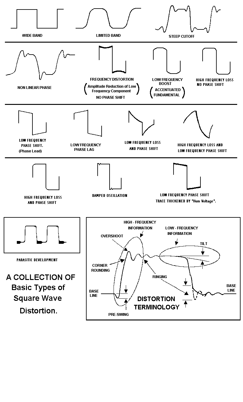
I'm currently testing my console and am trying to make sense of what I found regarding the trafo output of the 2-ACA summing and buffering board. With no load I get a nice representation of the 8k square wave (looks pretty much exactly as the "signal generator" [Moog Modular] puts it out). This is measuring pin 2 to ground.
But with the converter input connected the signal changes to a higher amplitude but more triangle/sawtooth like pattern. The converter shouldn't put a lot of load on the signal, and the discrete op amp / output trafo combination should handle a modern converter input easily.
Any idea what's going on here and what to do about it? Thanks!


