Older P&G fader question

GroupDIY Audio Forum

Help Support GroupDIY Audio Forum:

This site may earn a commission from merchant affiliate links, including eBay, Amazon, and others.

boji

Well-known member
Joined
Jan 6, 2010
Messages
2,377
Location
Maryland, USA
q8ka1jJ.jpg

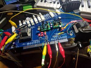
So...good news, I alligator clipped up my console's proto left card and from input to direct out passes audio and is nice and quiet (whew, that's a milestone and a relief).

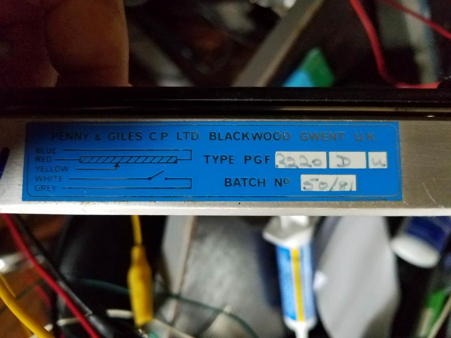
One thing I'm noticing is the old 10k P&G I'm using attenuates well, but doesn't bring the input down all the way silent.

I should mention the faders are from the 80's and definitely need new bushings. Of course rocking the slider perpendicular to its natural course of action it makes the volume blip in and out, but when I keep the contacts on the strip with a fair amount of pressure,  I can still hear some of the signal.  Is this normal / why we have a mute button?


This is why many Faders have a switch contact in the lowest position.
Neumann for example used this to mute (short) the output with a relay.
(I can measure a 30dB difference in Faders with a broken relay)
 
I haven't opened a P+G in decades, but they had PFL and mute microswitches in the closed position, microswitch contacts can get dity/corroded, often easier to replace the switch than attempt to clean them
 
Ah! Excellent, that explains a lot. Thank you very much yall!

I'll cotton ball a track or two and measure.

"PFL and mute microswitches in the closed position,"  Is this a sort of 'AFL/PFL' switching function? That's a cool trick!
 
Its been decades since I looked inside a P&G but as I recall they were pretty robust and respond well to cleaning. A friends console had orange juice spilled down inside the faders and they cleaned up nicely.

JR
 
The other thing that is important with any type of fader is how you wire up the 0V return. If you send 0V to the fader from the source and just bring the wiper back to the receiving amp you will often have a small bleed through signal due to the length of wire and track from the fader, to the source and then through the PCB tracking to the 0V reference point for the receiving input. To avoid this you should instead take the 0V from the fader bottom straight to the receiving amp input. There is no need for a connection from the source 0V to the fader 0V.

Cheers

Ian
 
boji said:
"PFL and mute microswitches in the closed position,"  Is this a sort of 'AFL/PFL' switching function? That's a cool trick!

Most decent manufacturer offer mechanical switches options at fader end
there is various use for it, hard audio bypass/mute, as any signaling/logic function like fader start in broadcast (by the time you want a turntable start as soon as you push the fader, or ONAIR light when you open mic channel.

Side question, why using old fader if you build/design a new desk ?

Best
Zam
 
"Side question, why using old fader if you build/design a new desk ?"

Cause I got 40 of em' and they were nearly free.  :) 

Replacing bushings / contact brush would be 1/3 the cost of new ones. Before I repair them, I'll try and determine how much life is left on the resist strips. So far I see no serious pitting, discoloration or ceramic peeking thru, but they are definitely friction glossy. I'll post a few picts in a bit.

Edit: When I first got them I remember emailing P&G and they said in so many words the way in which they make them hasn't changed in 50 years, at least as this applies to the 3k series.

Mo' Edit: 
"The other thing that is important with any type of fader is how you wire up the 0V return."
Reviewing skiz now! Thanks Ian.
 
Martin Griffith said:
I haven't opened a P+G in decades, but they had PFL and mute microswitches in the closed position, microswitch contacts can get dity/corroded, often easier to replace the switch than attempt to clean them

However, you have to be very careful if you do replace any of the microswitches as they need a jig to set them up so they trigger at the correct point in the slider travel.

Cheers

Mike
 
The other thing that is important with any type of fader is how you wire up the 0V return. If you send 0V to the fader from the source and just bring the wiper back to the receiving amp you will often have a small bleed through signal due to the length of wire and track from the fader, to the source and then through the PCB tracking to the 0V reference point for the receiving input. To avoid this you should instead take the 0V from the fader bottom straight to the receiving amp input. There is no need for a connection from the source 0V to the fader 0V.

Also my apologies Ian, but I am not fully appreciating what you said. Looking online I saw a few examples where it looked like they tied the input signal to both the bottom and the wiper, omitting use of 0v altogether...

Below is how I have it presently wired.

VB1CRjI.png


Edit: It will be fairly simple to sort out. I just need to try all variations.
 
Hi Boji,

The faders in your picture are a much later generation than I thought you meant so ignore my comment about the microswitch set up. 

It looks like you have a simple 3-wire fader with no ground compensation and so will have to take into account what Ian has pointed out with respect to where you connect the ground wire in order to get a good quality 'short' in the return path with the fader down.

Regards

Mike
 
This is old news when engineering for deep fader kill...

The fader ground, and the post fader gain stage ground reference need to be the same ground, so when wiper is all the way down it is presenting no voltage difference to the post fader gain stage to amplify.

The (red?) wire for fader ground will be carrying current drawn through the fader, this current will cause a tiny voltage drop in that red wire. It is not unusual to bring a separate wire back from that fader ground to serve as the gain stage ground reference so when wiper is all the way down there is no voltage to amplify.

Some faders have 4 wires or more (not including switches kind of like Kelvin test leads).

JR


Thanks JR and others, sorry to belabor a known solution. As it turns out the fader I was testing was in fact a bit noisy at lowest setting. Trying another before cleaning produced quieter (but not entirely silent) results. Here's what I've found with hookup variations:

ap38oXt.png


Also hooking Audio 0v at edge connector right below A1/A2 was no quieter than at fader molex.
 

Latest posts

Back
Top