freshtapescent
Well-known member
- Joined
- Jan 25, 2014
- Messages
- 45
Reeeaaally stoked about this. Appears new for 2018- anyone built it yet or at least have a BOM?


")
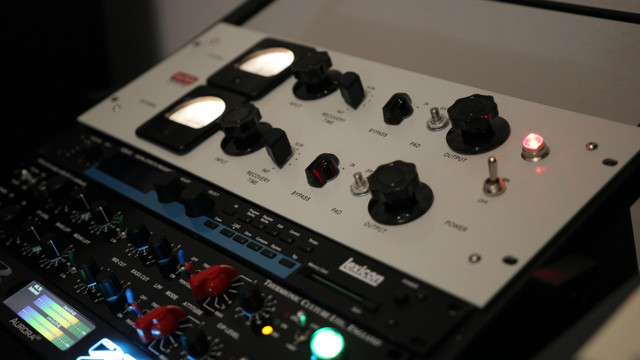
FarisElek said:Old thread but this seemed like the best place to post.
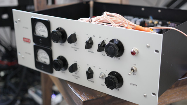
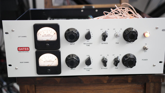
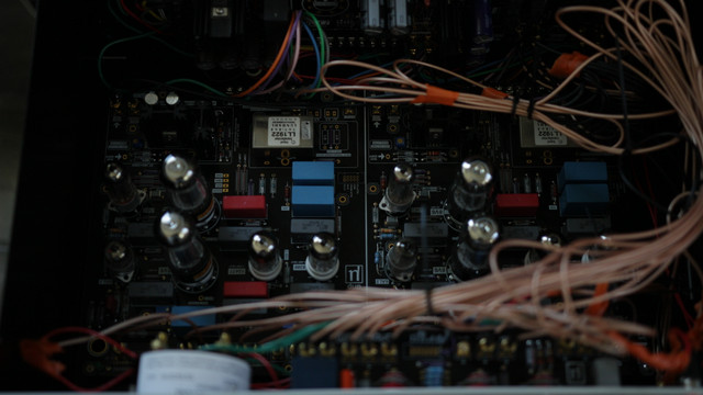
Currently building this Dual Sta Level by drip.
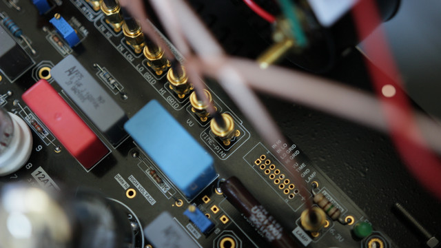
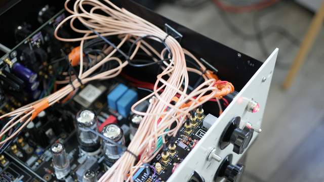
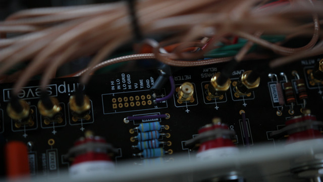
It has a revised board and i'm stuck on the PSU because of my lack of knowledge on it. The eratta's Greg posted are for the older board and are for using a solid-state PSU for two channels.
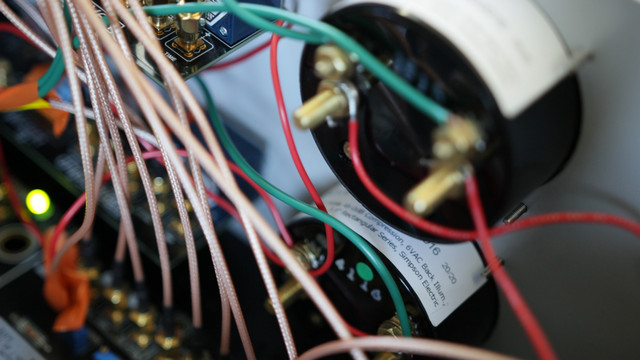
Does anyone with experience and perhaps someone who has already built this be able to explain to me how to fill out the PSU to use the 5AR4 for two channels? (I'm actually going to use a 5y3 I already have.
Thank you,
Ryan
FarisElek said:It has a revised board and i'm stuck on the PSU because of my lack of knowledge on it.
FarisElek said:The eratta's Greg posted are for the older board and are for using a solid-state PSU for two channels
FarisElek said:or a 5 watt - 10 w 100 ohm resistor in no choke .
Enter your email address to join:

