Ok, I did what I could on one of these with fewer alligator clips than I would've liked. I'll dig for some more leads and try again tomorrow.
So, if I've done things correctly, Voltage ratio is 1:1, or considering the center tap 2:1+1. To clarify, 1kHz at 1V in to pins 3-4 measures 1V on pins 8-2, and 0.5V on pins 8-1, 1-2
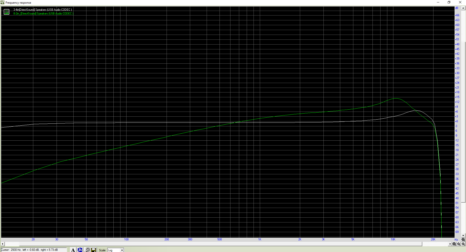
I ran a few tests with Rightmark audio analyzer and ended up with some encouraging results. Below is a frequency response graph comparing the wiring it "backwards" and "forwards" the white line is pins 3-4 as the primary, 8-2 as secondary, the green plot is 8-2 primary and 3-4 secondary. Let it also be noted that the input gain knob on the USB interface was at about +4dB using pins 3-4 as the primary, and at about +40dB using pins 8-2 as the primary.
Based on the plot, I think it's safe to say this is an audio transformer, primary across pins 3 and 4, secondary across pins 8 and 2, center tapped at pin 1. Can we infer a rough idea of the impedance ratio from the input gain difference? I don't have many pots/variable resistors handy to actually measure it. I'll try to play with this more tomorrow if there's time.
Would love any feedback re: my results and/or any flawed logic or methodology.
Here's the plot:


")