


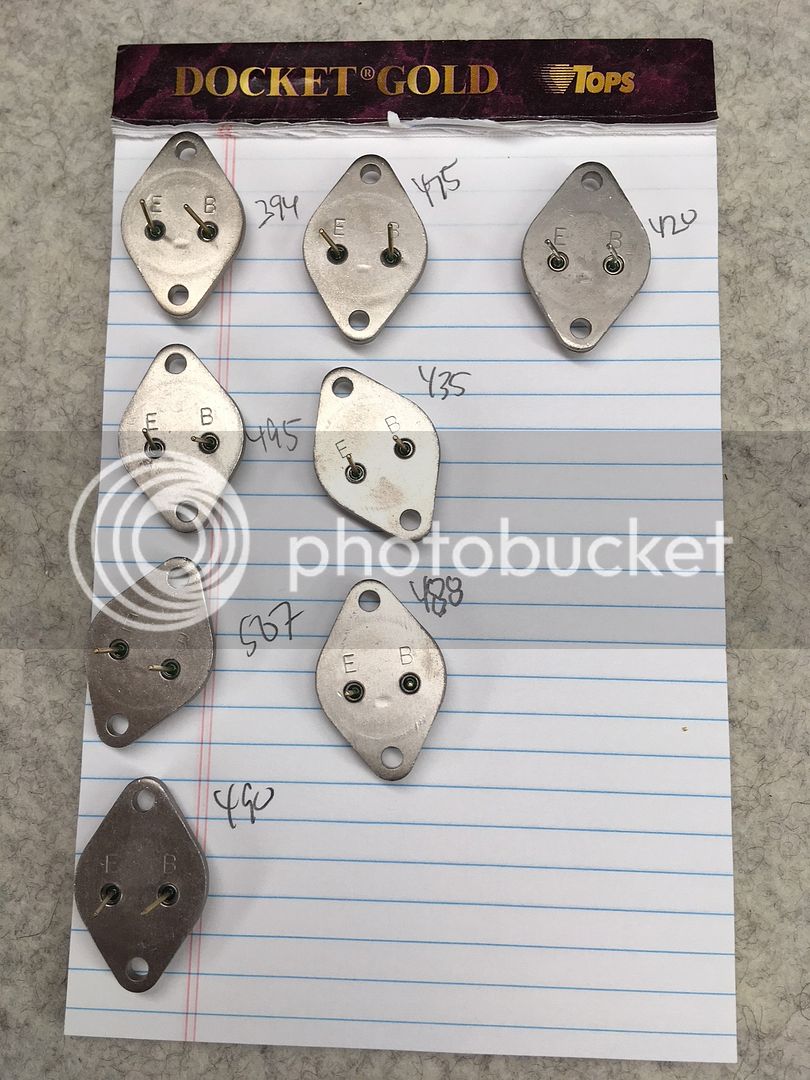
The die in the OP is 3.5 mm square, per the attached picture.
Per the IEEE history paper I posted earlier, the die was 4.6 mm square in 1960. I'm not sure if the die shrank heading into the early -mid 70s.
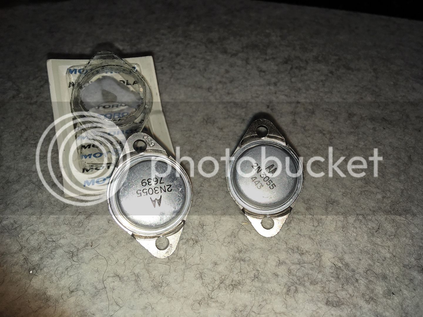
But the scratched up top plate and the wrong font tells me my batch are not Motorolas. I think someone sanded off the original label and imprinted the new label.
So in the trash they go. Thank you all for the help. Luckily they were very cheap.
Edit: the roughed up aluminum top plate and font both appear to be consistent with vintage Motorola 2n3055 after all.
Per the IEEE history paper I posted earlier, the die was 4.6 mm square in 1960. I'm not sure if the die shrank heading into the early -mid 70s.
But the scratched up top plate and the wrong font tells me my batch are not Motorolas. I think someone sanded off the original label and imprinted the new label.
So in the trash they go. Thank you all for the help. Luckily they were very cheap.
Edit: the roughed up aluminum top plate and font both appear to be consistent with vintage Motorola 2n3055 after all.


")

