One golden transistor to create noise in a drum machine

GroupDIY Audio Forum

Help Support GroupDIY Audio Forum:

This site may earn a commission from merchant affiliate links, including eBay, Amazon, and others.

living sounds

Well-known member
Joined
Jul 26, 2006
Messages
3,935
Location
Cologne, Germany
A story is circulating the web about rejected transistors used to generate noise in the TR-808 drum machine as a special sauce unobtanium kind of component. After the stock dried up they supposedly stopped making the drum machine.

http://secretlifeofsynthesizers.com/the-strange-heart-of-the-roland-tr-808/

What do the pros here think? I own a DIY 808 (Yocto) and have messed with the noise circuit but have yet to achieve the papery-metallic quality of the original. Can it really be that hard to recreate with "normal" components?
 
Ahh, there's nothing like the feeling you get when using an original piece of gear. Unless you know for sure what the circuit is really doing, there will always be doubt about a clone of some circuit. I made a Neve pre but I don't REALLY know if it's right because I have never studied an original.

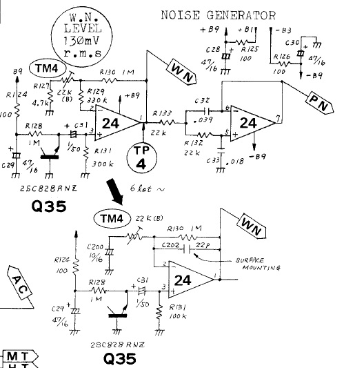
So is this the circuit with he 2SC828?

u3f4tQ6.jpg


Everything around the emitter junction is high impedance at all frequencies so even if the emitter junction has some weird impedance variations, they wouldn't be in the OA output.

I would think this should be just white noise. It even says in the circle "W. N. LEVEL 130mV r.m.s" which suggests white noise level 130 mV RMS which is 368 mVpp. Gain of the OA is ~70-100 depending on which of the two circuit variations is being used but that means 368 / 70 = 5 mVpp output from this infamous transistor. This actually seems low to me but I've never actually played around with a circuit like this so maybe someone else can comment on that.

Whatever the noise output of that circuit is, it can almost definitely be exactly replicated. It's just noise that needs to be boosted anyway so if it's missing lows or has a little mid boost, that can easily be tweeked.

If you have access to an original TR-808, make a probe with a 150 resistor to the op amp output (TP4) on the end of a short well shielded cable w/ shield to ground of device and then directly into a high res digital audio interface. Do NOT turn on 48V or you will destroy the op amp! Record 10 seconds of the noise output. That recording can be analyzed in Matlab or Octave to produce high res frequency spectra.

Note: Generally, if you're not well experienced with electronics repair, I do not recommend opening a valuable original instrument like a TR-808 because you can cause harm. For example, even small amounts of static electricity discharged into digital IOs (yes, there is some old school digital bits in there) can destroy their gates. I saw a video of someone working on a Yamaha CS60 and they destroyed a bunch of chips poking around (mostly because the chassis is wood but plastic isn't any better!). So make sure everything is grounded and you're not wearing a fleece vest and don't haphazardly poke around at things.

Note that it would not surprise me at all of original units sounded different from clones because, judging from a cursory look at the circuit, any electrolytics used as filters would dry out after 30 years and loose their filtering abilities.
 
Even though that noise is called "white noise", not all transistors do actually create pure white noise, but a lot of them do produce "white enough noise". I really can't imagine industrial scale selection for the purest of white noise for a percussive noise circuit. Seems a bit over the top, but then there's different sounding 808's.
You could put in sockets and try out a few resistors, or build a separate noise circuit to audit transistors (I have a tiny which has this circuit, as well as the later 4006 CMOS based digital noise circuit, but one can leave off the latter if not needed of course).
Let me know if you'd like a board.
 
A base-emitter junction backwards will zener around 6.8V and all zeners are known to be noisy...

Special mojo noise, sounds like kool-aid for the thirsty, while no doubt different processes can behave differently in subtle ways, I never taste tested noisy zeners.  If anything I added diode clamps to prevent reverse zenering that makes low noise transistors less low noise in the forward direction.

JR
 
The reverse-biased base-emitter junction to make noise has to be one of the more infamous "uses" (more like abuse) of a bipolar transistor. Using it this way surely exceeds both the max voltage and max current ratings of the reverse Vbe junction, so the transistor maker won't guarantee it in this circuit. If it changes characteristics or craps out, it's the circuit designer's fault.

This has some more details:

https://electronics.stackexchange.com/questions/289058/are-reverse-biased-transistors-stable

It's basically a zener/avalanche diode (that's just the mechanism - replacing the transistor with such a diode is, IMHO, unlikely to make the same noise, but since this particular transistor is unobtanium, it's worth a try), and there are at least two mechanisms that make noise, and the two noises have different characteristics.

IMHO, they should have used a diode for this circuit from the beginning. It wouldn't have "that sound" but it would at least give a consistent sound.

But yeah, I like the idea of recording and analyzing the noise from a "working" device - that'll at least tell you what you're aiming for. No doubt you could program an ARM processor to reproduce the noise, once you know what it is.
 
Roland isn't the only one to use a "special transistor" in this application.  This schematic says "Select for best noise:"

http://musicfromouterspace.com/analogsynth_new/OLDIESBUTGOODIES/NOISE/noisesource.html
 
It clearly will not be pure white noise: 1/f noise happens and often well into the audio band. Even the subsonic parts of 1/f rumble will modulate the audible hiss.

We are on the fringe of "good design" and I accept that it may be worth trying several/many/many-many parts until you get best sound or your ears fall off.
 
I always thought one way to make hiss/white noise in a circuit was to use a sub-par resistor with a lo-fi opamp... I'm mildly interested in adding such generator to a synth I'm working on atm.
 
efinque said:
I always thought one way to make hiss/white noise in a circuit was to use a sub-par resistor with a lo-fi opamp... I'm mildly interested in adding such generator to a synth I'm working on atm.
Different noise sources make different noise.  Back at my last day job we had a house number low noise IC that was graded or selected by the manufacturer for the frequency response of the noise floor (specifically to parse out excessive 1/F noise that is undesirable in audio path noise floors. ) Customers like to listen to stuff WFO and make quality judgements based on the "sound" of the noise floor.

JR

PS: I recall back last century making noise using a multi stage digital ripple counter (multiple divide by 2 stages in series). Summing different taps created a pseudo random noise. Not random enough for purists but good enough for some measurements. I couldn't find an app note using google and gave away most of my old application lit but IIRC it was done with 4000 series CMOS (CD4020?).
 
IMHO, they should have used a diode for this circuit from the beginning. It wouldn't have "that sound" but it would at least give a consistent sound.

Peanut gallery aside: If they used a diode from the beginning, then that would have been the holy grail sound.

Can someone tell me why it is so important to recreate a vintage DM sound to exacting specifications? Does it have to do with peer vetting / beat maker credibility? To me it's a weird, fascinating whirlpool of esoteric concern.
 
speculations:

in the schematic the "so called" white noise is modulated by a 2pole lowpassfilter to create pinknoise. not sure but, the poles by them selfs are at 185hz and 400hz. (perhaps a slow start at 185hz and then full 2pole at 400hz) 

if roland wanted a realistic pink noise then i guess the 1/f flat corner within the "so called" white noise should have been at 400hz or higher. so they screend alot of transistors and selected transistors with corners that was located high enough in the spectrum.

varying values, both with the transistors and the tolarance in the R and C in the filter, gave some difference in sound between each unit.

also, W.N. LEVEL 130mV RMS, could mean the level above the corner. (>400hz)
and not full bandwidth.

 
further on, to have a white noise with a rise in amplitude below 185-400hz  could be because the designer had room acoustics in mind as we find the schroeder transistion ni that region.

the snare wasnt supposed to sound like it was standing in a dry, acoustical over treated enviorment, but instead in a normal room of some kind.
 
boji said:
Can someone tell me why it is so important to recreate a vintage DM sound to exacting specifications? Does it have to do with peer vetting / beat maker credibility? To me it's a weird, fascinating whirlpool of esoteric concern.

My motivation is that I find it to be one of those "perfect" sounds. The 808 snare in a slow repetitive beat has an almost hypnotic quality. Doesn't really work without that special sizzling noise.
 
living sounds said:
My motivation is that I find it to be one of those "perfect" sounds. The 808 snare in a slow repetitive beat has an almost hypnotic quality. Doesn't really work without that special sizzling noise.

As far as sound design goes the white noise used in snares/hi-hats and synths is usually high passed... same goes for sweeps.

A lot of people use it as an effect to fill the gaps and compensate for the missing ambience/lack of high frequencies.
 
Back
Top