JW said:
So ostensibly the same 0VU reference (?)
VU does not mean volts. V means volts. VU means volume units which has to do with signal levels.
JW said:
Let's say we have a common +/-16VDC supply for an API unit or something. When connecting the power supply to a card, you'd want to connect 0V to 0V, but is it okay for that connection to be carried by the shield of a common 2 conductor (+ shield) cable?
Ideally the chassis ground should only connect to the power supply ground at one point. Usually earth ground coming in from mains is connected to the chassis right next to the mains plug. Then a wire from there to power supply board is the one point where they connect. Then from the PS to the main board.
Shields should only be connected at one end. If a shield is connected at both ends such that you are effectively connecting the chassis and PS ground together at more than one point, that creates a loop. A loop in the ground is potentially bad because a loop of wire is sensitive to electromagnetic interference.
Having said that, old guitar amps almost always have multiple ground loops formed by all of the jacks and pots bolted to the chassis but then also connected to signal ground at the inputs, effect send / return, reverb tank cables and so on.
If you want to shield a signal cable running out to the front panel, you should connect the shield at one end but not at the other. It doesn't really matter which end but my feeling is that usually the PCB end is used.
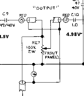
This standard practice in Urei gear like the 1176 and LA3A. You can even see how the shielding is done from looking at their schems. They're drawn like this:
You can see one end of the shield but the other end is dismissed as a squiggly line. That means the other end isn't connected. You might think the "INPUT" pot of the 1176 is an exception to this because it is connected at both ends but if you look carefully, it's actually not connected to ground at the pot end. It's completely isolated through a cap.
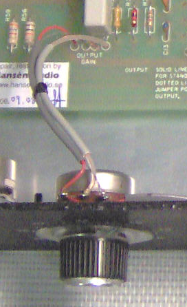
Here is a pic I found of the corresponding control in the 1176:
Note that in this case, because the pot also needs signal ground, it just takes it from one of the shields. So it's doing "double duty".
Now in practice, it's probably not really a problem if you connect the shield at both ends. If the ground is the same ground (meaning chassis -> shield -> chassis) that's actually perfectly ok (the chassis is where we want to shunt EMI anyway). If you have a shield connected to the PCB ground at one and and then also to chassis ground at the other end, that could pick up some hum from a transformer or some other source of EMI. But my guess would be that it's actually fine and it's not a problem. If you really want to know, you have to measure things. I measure the cr** out of everything. My favorite thing to do right now is to just make a recording and then do FFT plots with software.
But if it's a simple matter of opening it up and cutting the shield connected to the chassis, that might be a simple fix.