Problem with pultec gain makeup amp (roll off above 10k)

GroupDIY Audio Forum

Help Support GroupDIY Audio Forum:

This site may earn a commission from merchant affiliate links, including eBay, Amazon, and others.

shot

Well-known member
Joined
Nov 28, 2008
Messages
669
Location
Zagreb, Croatia
Hi,

I'm having an issue with gain makeup amp in my Pultec build.
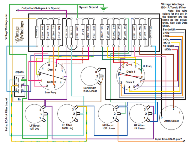
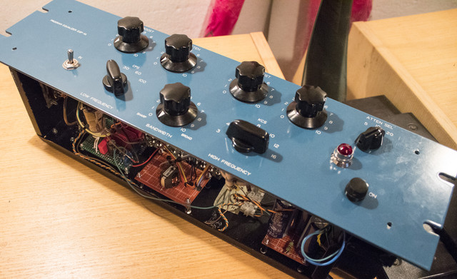
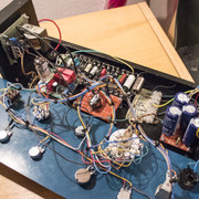
It is a sort of hybrid build with filter section based on Rainton/JBB/RecPro schematic (I guess this is original schematic) using Don-Audio inductor, and Ian's PSU and gain makeup amp. That is why I'm posting this in a separate thread not to clutter PoorMan Pultec build thread since it's not exactly that unit.

Filter section is working fine. I have no problem with it.

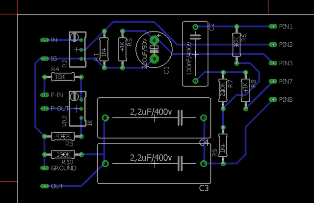
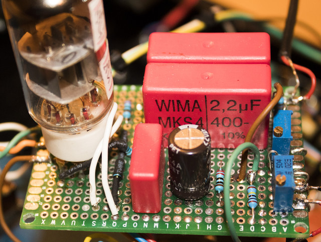
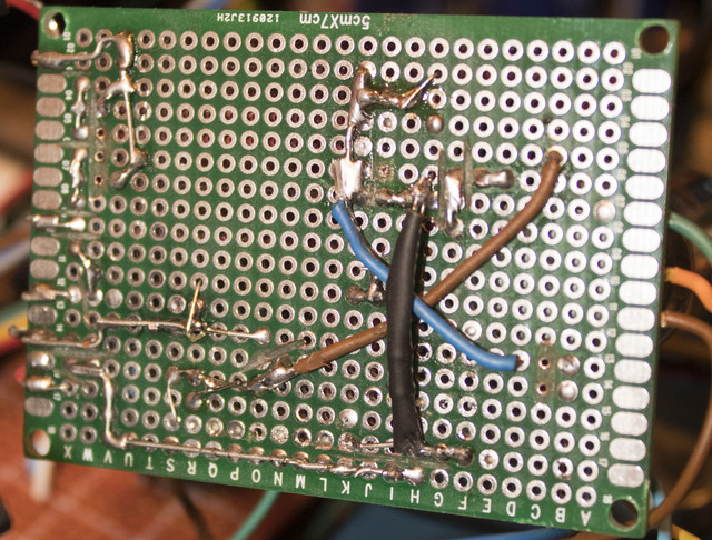
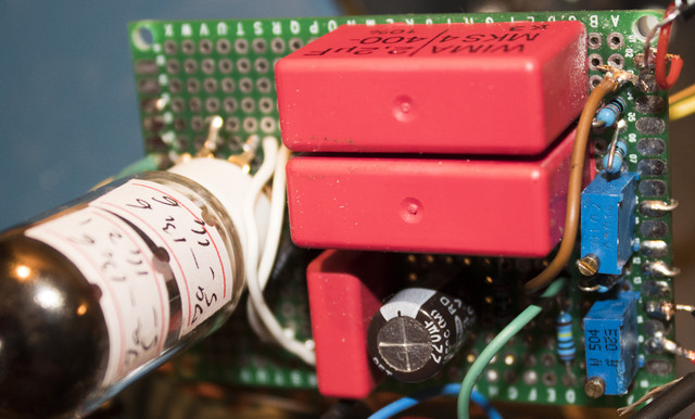
I've built Ian's tube gain makeup amp on veroboard. All parts triple checked, no shorts or unsoldered connections. It is Mu topology for 6922 tube (with RK = 220R, Rmu = 4k7) but I'm using russian 6N23P-EV tube that is supposed to be direct replacement to 6922 tube. I will order 6922 but it will take some time to have it delivered, and I somehow doubt it will make difference.

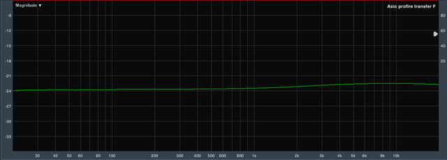
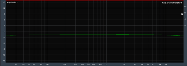
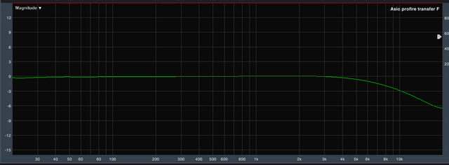
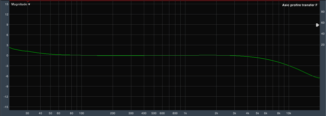
Problem I have is that the makeup amp is rolling off high freq, starting from around 3k to reach around -6db at 20k.
See attached measurement:


I've searched for a solution and only mention of similar problem was this post but it unfortunately remained unsolved

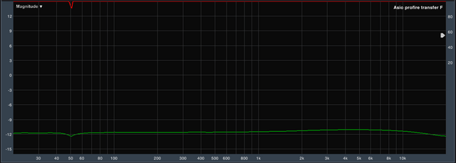
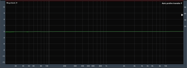
I have narrowed the problem to gain makeup amp since I've measured the secondary of the input transformer (OEP Z3003) and it's fine. Output of the filter section is also fine. But if I connect input tx secondary directly into gain amp, I also get HF rollof.
I've also tested if it makes any difference if I bypass output transformer (Stancor 600:600, unknown model no., taken from MCI console) and it's the same. 
Amp is working on 280vdc HT supply. I've checked trillion times and though it's on veroboard, I've built it correctly. In Ian's documentation it is specified to have 300vdc supply... could it be that this issue is due to underpowering? Could it be that this 20v difference is causing it?

Obviously, Ian Ruffrecords would be the ideal person to help, but if others had similar issues with Poor Man Pultec gain makeup board please share your thoughts!

I don'k now what else to try...
Help a fellow diyer!

:)

Luka
 
This is very odd, especially as you are the second person to report this. Using a 6N23P should not make any difference. I use them all the time for checking new designs. You do get the occasional dodgy one but mostly they are pretty good.

The circuit is very tolerant of HT voltage. It will work from 250V up to 300V with very little change in performance.

The most common cause of HF loss in tube designs is Miller effect. This is the multiplication of the anode to ground capacitance by the stage gain (about 30) which then appears between the grid and the ground. This capacitance then forms a low pass filter with the source impedance of whatever drives the grid. In guitar amps this effect is used to deliberately shape the HF response - hence the typical 68K resistors in series with inputs.

So there are two things that can affect where the HF roll of starts. First is the anode to ground capacitance. Inside the tube this is normally a few pF but poor layout can easily increase this. So perhaps your veroboard layout contributes to this.

The second factor is the source impedance.. At high frequencies the poor man's EQ should never present a source impedance of less than 5K so Miller effect should not start to occur until well beyond 150KHz.  However, you have a new filter section. If you can post its schematic we can work out if this is the problem.

Cheers

Ian
 
Thank you Ian for responding  ;)

The schematic I've used for the filter section is this one:
http://jbb.ru/schematics/1a-shem-p.htm (compliments to JBB and his build)

and I assembled it following those two diagrams:

http://www.mediafire.com/file/2b8py0igkenkh7l/Pultec_EQP-1A__layout_rev1_31.pdf (compliments to Rainton and his build)

and

Chris Preston's of VintageWindings.com


They are basically the same except in Rainton's diagram resistors are mounted around switch pins.
I've done them that way.

High freq rolloff is present when filter is engaged or bypassed. It's the same.

Here is the measured frequency response of the filter output (physically disconnected it from entering the makeup amp)

There is a rise of about 0.8db around 9khz!

About my veroboard makeup amp - I went with your poormans schematic and to some extent followed the layout you've done on your board. I first drew optimal layout in eagle and then arranged components following this design. It was too complicated to draw tube socket so I left pads that are actually wires to tube socket pins. Tube socket is on the right of the board. I had to use short wires to go from top right to bottom right to route to first three pins of the tube. This is not drawn on this design.
If it will be required, I can disassemble the board and take some detailed photos of it.
All the traces on my veroboard are as far apart as possible from each other and on those spots where they go closer I've cut the copper with dremel to be sure there is no way that leakage can occur.
This is my layout template I created for the veroboard layout:

ATTENTION - R1 and R9 are 220R (RK1,RK2) and RMU (R6) is 4k9 (two 10k resistors in parallel). Disregard the different values on this layout!

I've connected filter output to In pin and output of the amp from Out goes to output transformer. Pins P-In and P-Out are unused since bypass switch is part of the filter. Ground from the PSU is connected to IG. Heater H1 and H2 and HT supply are directly soldered to tube socket pins 4, 5 and 6.
Could my problem be related to different bypass switch arrangement (I guess not, but still asking :) )?
Could it be that the problem is with two 10k resistors in parallel giving 4k9 instead of specified 4k7 for RMU?

I hope all of this helps...

:)

Luka 
 
From the information you have provided I still think the most likely reason for the HF roll off is Miller effect. It looks like you have quite long connections to and from the tube and its associated components, especially the first anode, which might be the cause of this. Is there some way you can reduce these?

Cheers

ian
 
The only thing I could do is to rearrange the whole chassis to have makeup amp closer to psu.
I've put them on the opposite sides of the chassis so inevitably there is a long wire to pin6 from the psu. It's like 35cm long!

I'll try it over the weekend!

thanks

:)

Luka
 
shot said:
The only thing I could do is to rearrange the whole chassis to have makeup amp closer to psu.
I've put them on the opposite sides of the chassis so inevitably there is a long wire to pin6 from the psu. It's like 35cm long!

I'll try it over the weekend!

thanks

:)

Luka

Pin 6 is not a problem. That connection can be as long as you like. The important one is the one from pin 1 (first anode)and to a lesser extent pin 2. (first grid)

Cheers

ian
 
I was planning to do another board during this weekend, but so called "life" kicked in and I had no spare time.
I had time to take few photos, though they are not perfect since I didn't remove the board completely out of the unit.

When Ian said that the problem could be in length of wires connecting to pins 1,2,3, I immediately have suspicion to those two white wires that you can see between tube and film caps.  They are bridge from the top to the bottom of the board and they connect to pins 1 and 2.

But I'm thinking of completely redoing this board to have all the components as close to the tube socket as they can be.

Anyway, here are the photos:

(CLICK ON THE PHOTO TO ENLARGE)


:)

Luka

 
shot said:
....I immediately have suspicion to those two white wires that you can see between tube and film caps.  They are bridge from the top to the bottom of the board and they connect to pins 1 and 2.

It looks little bit messy but i don't think the white wires are the culprit.
Have you tested makeup amp by connecting  the input signal directly to  the input pin without the input transformer? Try to check the freq. response for different  settings of input trimmer. If you need a ECC88 for testing, I can borrow you one.
 
Thanx Milan!
Do you think it could be the tube?
I've tested two tubes that I have of this type. Both are 6N23P-EV. Haven't tested ECC88.
If you think that it could be related to tube I might come by and borrow one for a quick test!

Testing directly from the input transformer without any filter section was the first thing I did! I've captured frequency response of that but I didn't post it in earlier posts. No problems there. Here's the measured result

xlr in -> input transformer -> makeup amp -> output transformer ->xlr out

top baby names 1997

:)

Luka
 
I think it is unlikely to be the tube. It might be the output transformer. Good idea to divide and conquer so could you test frequency response with the transformer disconnected?

Cheers

ian
 
shot said:
Testing directly from the input transformer without any filter section was the first thing I did! I've captured frequency response of that but I didn't post it in earlier posts. No problems there. Here's the measured result
xlr in -> input transformer -> makeup amp -> output transformer ->xlr out

This looks god but you said earlier "But if I connect input tx secondary directly into gain amp, I also get HF rollof."
So I'm little bit confused right now.  Oke, could you do the test of whole chain but with disconnected electrolytic capacitor C1 on cathode resistor. The gain will be lower but I'm interested in freq. response.
Anyway, if you like to test another tube, drop me a PM .
 
Sorry, I had no spare time to do some tests earlier! Busy week...

I tried first to test what is the freq. response without output transformer. I tested that last week but it was just by taking signal with alligator clip from out transformer primary. This time I unsoldered it completely. It changed nothing. Still have HF rolloff...

Here's the pic:


After that I took out 220uf cap. As Moamps predicted, output level dropped by 12db. But here something interesting happened. At first when I powered the unit level went almost up to 0db with HF rolloff present. Than in next few seconds level dropped to -12db. HF rolloff seems to be present but now it is not that sharp. When you observe the pic, there seems to be slight wide high-mid bump by about +0.5db and then HF drops by 1.2db. Since I'm testing with regular audio interface I don't have reading above 20k, but I guess it keeps rolling off by small fractions even above 20k.
When I powered off the unit, level bumped up for a second back to 0db with that notorious HF roll off before signal completely died off.

Anyway, here is the pic of the frequency response without 220uf cap in makeup amp:


I have enough material in my drawers to do another board so I'll jump on it right now.  This time I'll try to reposition components to have everything as close to the tube possible to avoid miller effect as Ian suggested. It's easier to do another new board instead of messing up this one. If I try to rework this board I may miss something and create new set of problems.

Write you back when I do new board.
And if this new board would preform the same, Moamps will get a visit from fellow citizen to borrow a ECC88 tube for one afternoon!

:)

Luka
 
I've made a new amp board.
Seems that the problem is solved!

This time I didn't do veroboard but an self etched one. But more importantly, this time components were arranged differently and are much closer to the tube socket.

I didn't mount the board into the chassis yet so there's chance that something goes wrong there, but I'm keeping my fingers crossed that this is it!

Here's the frequency response on the output:
It's without output transformer - just input transformer into amp board and out unbalanced!


I'll post some more pictures soon and report what's going on when I mount it into chassis and connect the filter section.

:)

Luka
 
I realized I didn't write an update for few days. And a lot happened meanwhile!

When I built new amp board I thought I had everything fixed. And indeed, things did perform better. At least when I had connected signal from the input straight into new makeup amp board. That's when I had flat frequency response. It looked excellent at that point.

But things worsened when I connected the filter section. High frequency roll off was there, though not that prominent. It was around -3.5db at 20khz. Than I decided to try different topology in the gain amp. I switched from MU to SRPP. In that design my roll off reduced by one db. It was around 2.5db at 20khz.

Frankly, this was okay to me. This drop was measured but not audible and I considered it a great improvement from the initial 5.5db with MU design on veroboard. And I was totally ok to leave it as it is. But one thing that bothered me, and I noticed that only when everything was done, is that it had only 7db of maximum boost on high frequency knob. That's totally okay when doing vocals, but on some instruments like bass guitar it's barely noticable when pushed to maximum boost.

In the filter design I used (based on original schematic, also used on Rainton's and JBB's builds) 10k linear potentiometer on HiBoost position. Also worth noticing, unlike on Poor Man Pultec, this potentiometer is the point of entry of the input signal (after input transformer). I replaced it with 50k linear pot and first thing I noticed (and measured) is that output signal of entire passive filter dropped by 12db! But I had (almost) enough gain available on the trimmer on makeup gain board to compesante for this drop (I reached -1.1db with trimmer full open). Now I had +16db of maximum gain boost on high boost filter. Way more like it! But one more important thing happened also - no more HF roll off! It was prefectly flat! Well, almost perfectly flat since I measure very broad boost of 0.4db from 1khz up to 8khz. But this is truly irrelevant to me. I went to buy 25k linear pot and it is not creating such big level drop (around 10.2db) so that's just enough for input trimmer on amp board to keep up with it.

It seems that load on the input of the passive filter had to be increased for makeup amp to work well.

I was thinking of going back to MU design, but after some listening tests I figured SRPP sounds excellent. It has a bit more second harmonic than the third harmonic (MU measured 2nd and 3rd almost at same level) but I like how it sounds. I'll probably leave it this way. Also, when it comes to MU vs SRPP difference, I noticed that on my build MU design is working on aprox. 278vdc and SRPP is keeping power supply on 303vdc. Irrelevant I guess, just noticing the fact!

In the end I think this is it. Pultec works great! I know I created a hybrid and it's me to blame for that so I had a fair amount of troubleshooting, but in the end I enjoyed it! It's never fun if you're not forced to learn something new in the process!

Again - great big THANK YOU to Ian Ruffrecords and Milan Moxtone for assistance! When I lost all ideas you guys inspired me to go on!

:)

Luka
 
Back
Top