Aux sends and returns in a mixer project- what's your opinion?

GroupDIY Audio Forum

Help Support GroupDIY Audio Forum:

This site may earn a commission from merchant affiliate links, including eBay, Amazon, and others.
boji said:
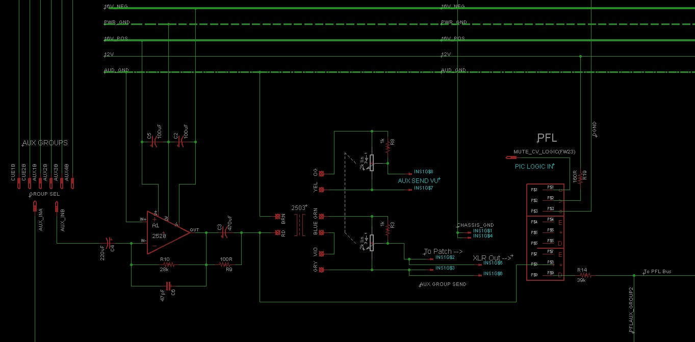
Yessr, thanks Abby.  R9 is not making much sense, but R1 I thought is part of A2 which is driving a 2503.
Ah! I didn't realize that. Then the exixtence of the primary is enough to guarantee low DC.
But I don't see how a xfmr ther would be of use, since the signal is not meant to go anywhere else than bus.
 
i'm not really sure but I believe that API uses a simple pot wired as a voltage divider after the ACA's transformer and that's it.
Thanks pahstah, yes, that's how Jeff's ACA/Bo has it-- straight from the old 70's API playbook.
Again, I inferred from a question Ian posed elsewhere about the need for TX1 to mean if it's not supplying balanced signal anywhere, why include it?  Sound / isolation-wise it couldn't hurt, but omitting it would make it possible to fit three aux sends on a pcb where otherwise only two would fit when using two tx's and two 2520's per send.

Boji, what i meant was that i believe that API uses a pot after the auxes ACAs but no booster after that, the signal is taken from the ACA tx to the balanced out
 
The old api mult ACA is for the bus to tape snds.  The reason for a TX is that is prefade insertion on the bus. It’s a  patch points to insert compression and such before the booster. 

Capi cards are recreations of those points in original api consoles.  You are using these for cue snds and echo snds.  I don’t think you need the boosters if you use a balance 600 ohm 3 section pot for output.  Also the cards have 4 or 2 circuits so hence use the 4 transformers for 4 sends.  Use 2 cards for 6 + 2 extra for pfl solo etc. 

Also you don’t need solo on aux.  just extend to an open input on your monitor controller. Or add a source switch.  I added a 10 position switch to my console .  It’s has 2 DPDT switches per selector switch so will switch stereo balanced lines passively.
 
Sorry if this has already been said, but when looking to old legacy mixers for design advice try to hold them in context for their time. Back in the day effects were very expensive and rare. An entire studio might only have one reverb to use in mixes, unlike today where free digital reverbs come as promotional gifts inside cereal boxes.  8) So a legacy console design will be biased toward busing effects to optimize utility of the only one or two effects. Premium consoles might have multiple effects buses.

Today an optimal architecture could lean toward more expansive insert capability so more available effects can be used on multiple channels, perhaps a premium version of this would be to provide multiple inserts per channel on at least a few channels.

Of course this all depends on your personal mixing style and effects gear inventory and plan.

JR
 
Happy Thanksgiving Everybody!

But I don't see how a xfmr would be of use, since the signal is not meant to go anywhere else than bus.
Thanks Abby, which one the 2503? I'm not sure I understand, since signal is being summed from the aux bus, balanced, then sent to patch with mult to xlr. No returns card has been considered yet as I'll try the channel injection thing Ian and Fazer suggested.
Boji, what i meant was that i believe that API uses a pot after the auxes ACAs but no booster after that, the signal is taken from the ACA tx to the balanced out
Thank you Pahstah, more confusion on my part; doing some different thread reading and listening to advice here, to take signal from the ACA to balanced send and yet include volume, my understanding is you can variate the nfb resistor and achieve ok results despite the nfb cap remaining constant or, you can bridge the tx with a pot, but that would make it unbalanced out, or lastly you can do some interstage thing similar to my posted skiz (Perhaps going with the quieter 990 on A1 as Abby suggested) which retains balanced out and some volume play. I think the only other way to do it is to use a stepped switch and high precision resistors on the output tx. This might be the best space saving solution as it means only one opa is necessary.
Also you don’t need solo on aux.  just extend to an open input on your monitor controller.
Thanks Faze,
boy you guys are putting me on my toes. :)  I see the absence of pfl fine for cue, but I figured if I was adjusting fx input I might want to check the send on the pfl bus prior to going to channel, with returns afl being handled by the channel insert.
 
boji said:
Happy Thanksgiving Everybody!


... my understanding is you can variate the nfb resistor and achieve ok results despite the nfb cap remaining constant or, you can bridge the tx with a pot, but that would make it unbalanced out,

I think that is where you are misunderstanding. You can do a pot on the secondary of the transformer without unbalancing it. It is what in the past I have called the 'Neve trick'. It was done on some outputs of broadcasts desks for instance. A 2K pot across hot and cold, a 1K resistor from hot to wiper and output between cold and wiper. Attached is an extract from the Neve 5315-120P standard broadacast mixer block diagram showing how it was used on an aux out.

Cheers

Ian
 

Attachments

  • Screenshot at 2018-11-22 21-22-58.png
    Screenshot at 2018-11-22 21-22-58.png
    45.9 KB · Views: 45
Happy Thanksgiving Everybody Westerners.  ;D

Wow ok I stand corrected pahstah.  Thanks Ian, I'll try that out tonight! 
 
Sorry if it this has already been said, but when looking to old legacy mixers for design advice try to hold them in context for their time.

No, not all all JR,  I love it when you guys share your perspectives.
 
I'm fairly thickheaded. To be clear, you mean like this?
Edit: Also, would sticking a two deck pot with the same wiring and resistor value on the -6db vu outs track the volume changes for send?
tGqlhNw.jpg
 
boji said:
Thanks Abby, which one the 2503? I'm not sure I understand, since signal is being summed from the aux bus, balanced, then sent to patch with mult to xlr.
Well, I must admit I am sometimes puzzled up to the point where I don't know if you're talking about an Auxiliary group (please don't use the word "bus" for that), or an FX return.

This might be the best space saving solution as it means only one opa is necessary.
In my experience, space saving is not a good inspiration. I've always found that real estate is more a concern for front fascia than for the PCB. Doing things as they should (meaning putting what's good to have , but not too much, without having to be clever - often something you might regret after the fact) is essential.
 
boji said:
I'm fairly thickheaded. To be clear, you mean like this?
Edit: Also, would sticking a two deck pot with the same wiring and resistor value on the -6db vu outs track the volume changes for send?
More or less. The resistor wants to be from pot silder to cold (not sure if that is what I said previously) but otherwise the aux out pot circuit is correct. I don't think you need to mimic the pot for a VU meter feed. The output impedance after to pot is less than 400 ohms so you can slap a VU straight across it. Is the VU meter buffered?

Cheers

Ian
 
Doing things as they should (meaning putting what's good to have , but not too much, without having to be clever
That sounds like good advice for writing as well. :)

The output impedance after to pot is less than 400 ohms so you can slap a VU straight across it. Is the VU meter buffered?
Yes, buffered meters, TL072.  Good idea, as then the -6db out can be used as a direct out for re-amping and such. Thanks Ian.

Edit: By the way, R9, 100ohms, what exactly is it doing?  Self's book, "Small signal Audio design" is great, but there isn't much about transformer circuits. Might anyone have a recommendation that focuses on solid state designs with tx's?
 
boji said:
Edit: By the way, R9, 100ohms, what exactly is it doing?  Self's book, "Small signal Audio design" is great, but there isn't much about transformer circuits. Might anyone have a recommendation that focuses on solid state designs with tx's?
The resistor is used to tame the resonance of the LC circuit constituted by the coupling cap and the xfmr's primary. There are two possibilities for that: one is to increase the impedance of the drive circuit (that's what happens in tube circuits naturally), but tehre is a penalty in terms of throughput. The other possibility is to shunt the coupling cap with a resistor; obviously it workd only with a drive circuit that has very small DC offset. Magnetization of the magnetic circuit due to DC offset is reduced significantly.
 
Hi Boji,

this is how the aux send output is wired in an api 1608.
From the pot the signal goes to the output connector and to a tl071 used as a buffer for the vu meter.

Paolo
 

Attachments

  • Api_Aux_Send.pdf
    889.5 KB · Views: 25
Thanks abby for the breakdown!  I appreciate it!

Also thank you pahstah. That is quite clear. It mirrors CAPI's ACA skiz.  Knowing it is still deployed on API's modern desk is also good to know.  I'll go with it.
For sake of understanding, Ian's add of the 1k pulldown and higher pot value I venture to guess is due to neve's tx having a higher minimum output impedance requirement (600ohms). Edit: Or is it due to the turns ratio?
 
boji said:
Thanks abby for the breakdown!  I appreciate it!

Also thank you pahstah. That is quite clear. It mirrors CAPI's ACA skiz.  Knowing it is still deployed on API's modern desk is also good to know.  I'll go with it.
For sake of understanding, Ian's add of the 1k pulldown and higher pot value I venture to guess is due to neve's tx having a higher minimum output impedance requirement (600ohms). Edit: Or is it due to the turns ratio?
The API schemo indicates a Log pot. Neve apparently used a Lin pot; it is quite customary to steer the taper of a Lin pot with a resistor to make it behave somewhat like a Log.
 
The API schemo indicates a Log pot. Neve apparently used a Lin pot; it is quite customary to steer the taper of a Lin pot with a resistor to make it behave somewhat like a Log.
Now that I do remember reading in Self's book!  ::) Thanks for the reminder.
 
abbey road d enfer said:
The API schemo indicates a Log pot. Neve apparently used a Lin pot; it is quite customary to steer the taper of a Lin pot with a resistor to make it behave somewhat like a Log.

And the reason is the taper of a LIN pot is better controlled than that of a log pot. Repeatability and matching of slugged LIN pots is better than that of LOG pots.. This was certainly true back in the 70s but production techniques have moved on since then. However, most log pots are these days are basivally two LIN tapers in series.

Cheers

Ian
 
ruffrecords said:
And the reason is the taper of a LIN pot is better controlled than that of a log pot. Repeatability and matching of slugged LIN pots is better than that of LOG pots.. This was certainly true back in the 70s but production techniques have moved on since then. However, most log pots are these days are basivally two LIN tapers in series.

Cheers

Ian
Opinions vary... pot tapers are generally about accuracy of a screened carbon ink. Tapers are ratios and actual resistance is also a function of the cured ink resistance. Slugging linear pots combines taper errors and bulk resistance.

Back in the 70's I liked alps pots and they specified tracking for audio taper down to something like -40dB. In a 4 pole crossover frequency pot I had to have my technician measure and add trim resistors to make the tracking even better.

These days I am thankful for DSP....

JR 
 
JohnRoberts said:
Opinions vary... pot tapers are generally about accuracy of a screened carbon ink. Tapers are ratios and actual resistance is also a function of the cured ink resistance. Slugging linear pots combines taper errors and bulk resistance.

Back in the 70's I liked alps pots and they specified tracking for audio taper down to something like -40dB. In a 4 pole crossover frequency pot I had to have my technician measure and add trim resistors to make the tracking even better.

These days I am thankful for DSP....

JR

At P&G, at least, tapers were  / are ( It was a while ago I was there)  trimmed manually on the production line - removing ink to get the taper within spec'. IIRC they were specified down to -40dB too .
 

Latest posts

Back
Top