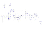
Help with modifying Circuit please

GroupDIY Audio Forum

Help Support GroupDIY Audio Forum:

This site may earn a commission from merchant affiliate links, including eBay, Amazon, and others.
Ok. I've read that page and "sort of" got the idea but I can't figure out a real solution to have the tone stack for both clean and dirty channels driven by the DC coupled cathode follower...the only things I can think of is using V1A as gain stage of V2B but I don't know if that's possible and would imply quite a bit of arrangement or using V2A instead of V1A in the Clean Channel.....
Anyway, I came up with this which is probably wrong because of the Clean pot placement before the stage but I can't come up with more ideas right now :)


Maybe using a 4P3T footswitch would allow to switch in the Clean Pot (between the Cathode Follower and it's gain stage) but unless there really is no other way I'd rather look for some other option.

Some hints/leads would be seriously appreciated :)

Cheers
Sono
 
Some help pretty please.....

I found another similar schem but the clean channel is the same as my first one...
http://guitar-gear.ru/wp-content/uploads/2016/04/Hot_Box_scheme.jpg
 
I have to say the way the tone stack is loaded with a 25k presence pot is quite surprizing. However, it seems it should do what it is intended to do, except it attenuates the signal by about 15dB. Is it intended? I don't know...
Now, SW3 bypasses one stage and there is no way to compensate the gain difference. I would think a pot at the output of V1b would be desirable.
Also SW4A1&B1 switch the grids, which don't have a grid leak, so you can expect a huge pop when switching.
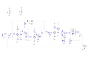
 
Abbey Road,

First of all, THANKS for taking the time to examine the schem and help me out on this one :)

abbey road d enfer said:
I have to say the way the tone stack is loaded with a 25k presence pot is quite surprizing. However, it seems it should do what it is intended to do, except it attenuates the signal by about 15dB. Is it intended? I don't know...
This circuit is essentially a preamp in a stompbox that can be put in front of the preamp of an amp. In such position it is going to add many gain stages in front of however many gain stages the amp already has and it’s going to be LOUD. OR it can be plugged into a power amp or into the return of an amp’s loop (bypassing the internal pre)...

This is where the presence control comes into play: it will probably be a bit bright when used as a stomp. The presence trimmer can be used to dial this back. As a pre the power stage is likely going to deal with the brightness of the pre so it can be turned up or just tweaked to taste.

BTW, I just realized that SW4.A should probably be placed AFTER the Presence trimmer (since its function is to choose the position of the circuit) and both trimmer and switch can be set according to the position choosed (in front of an amp's preamp or in its FX loop) as a "set and forget" setting. Am I right?

abbey road d enfer said:
Now, SW3 bypasses one stage and there is no way to compensate the gain difference. I would think a pot at the output of V1b would be desirable.
Ok. I thought R18 would compensate for gain as a 1M pot half way. Maybe I should convert it into a 1M pot then? Or the whole R17/R18/C16 cluster is wrong?  ???

abbey road d enfer said:
Also SW4A1&B1 switch the grids, which don't have a grid leak, so you can expect a huge pop when switching.
Ooops, maybe I should have put C1/22nF-R4/1M-R3/1K between SW4.B1 and V2A's grid? Like so:


And replicate C1/22nF-R4/1M-R3/1K between SW4.A1 and V1A's grid?

Again, I really appreciate your time and help :)
Cheers
sonolink
 
sonolink said:
This circuit is essentially a preamp in a stompbox that can be put in front of the preamp of an amp. In such position it is going to add many gain stages in front of however many gain stages the amp already has and it’s going to be LOUD. OR it can be plugged into a power amp or into the return of an amp’s loop (bypassing the internal pre)...

This is where the presence control comes into play: it will probably be a bit bright when used as a stomp. The presence trimmer can be used to dial this back. As a pre the power stage is likely going to deal with the brightness of the pre so it can be turned up or just tweaked to taste.
I understand all that, but my concern is that when you bypass it (going through the pot IMP-Matcher) there is a possivle huge level bump.

BTW, I just realized that SW4.A should probably be placed AFTER the Presence trimmer (since its function is to choose the position of the circuit) and both trimmer and switch can be set according to the position choosed (in front of an amp's preamp or in its FX loop) as a "set and forget" setting. Am I right? [/quote]


I thought R18 would compensate for gain as a 1M pot half way. Maybe I should convert it into a 1M pot then? Or the whole R17/R18/C16 cluster is wrong?  ???
Gain around V1b is about 8-9. If you want to compensate, you need a divider of about the same. I would say 470k/68k. Remember that an audio pot at mid-rotation attenuates by about 20dB (10:1).

Ooops, maybe I should have put C1/22nF-R4/1M-R3/1K between SW4.B1 and V2A's grid?
Yes, but you don't need C1.

And replicate C1/22nF-R4/1M-R3/1K between SW4.A1 and V1A's grid?
Yes, and again you don't need the cap.
 
abbey road d enfer said:
I understand all that, but my concern is that when you bypass it (going through the pot IMP-Matcher) there is a possivle huge level bump.

You're probably right but that doesn't really worry me. The idea of that switch is to:
1-decide to use the stompbox in front of an amp OR in front of a Poweramp.
2-Put the switch in the appropriate position
3-Switch on stompbox and amp
4-Adjust Presence pot to taste
5-Play :)

Hence my comment "I just realized that SW4.A should probably be placed AFTER the Presence trimmer (since its function is to choose the position of the circuit).

If you decide to change the position of the stompbox you would have to switch the amp off anyway to avoid bumps.
It's a "set and forget" thing. It's purpose is not to switch while playing.

I will correct the schem according your suggestions and report back.

Thanks again a LOT for your input Abbey :)
 
Have you really tested the circuit with the presence pot?
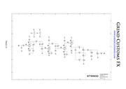
My sim shows that the Treble control acts as a "rocker" between bass and treble, which may be acceptable, but teh Bass control acts more or less like a switch, with the variation concentrated on the first percent of rotation.
IMO this circuit should be placed at the anode of V2A, with a 500k pot and a 1nF cap.
 
Hi Abbey

abbey road d enfer said:
Have you really tested the circuit with the presence pot?
Not yet. I was about to build a proto when DMP forum member brought up some points that I corrected. Initially the Clean channel didn't have a tone stack, like the original circuit schem:


abbey road d enfer said:
My sim shows that the Treble control acts as a "rocker" between bass and treble, which may be acceptable, but the Bass control acts more or less like a switch, with the variation concentrated on the first percent of rotation.
IMO this circuit should be placed at the anode of V2A, with a 500k pot and a 1nF cap.
You mean the whole tone stack or just the Bass control?
Not that I'm sure this is of any use, but the circuit is supposed to be a replica of the Marshall Plexi, and its tone stack is a copy of the Plexi like this one for instance:
https://el34world.com/Hoffman/files/Hoffman_Plexi50.pdf
I'm not meaning to say you're not right, just saying that it seems to be a known circuit and that it sounds great. Of course that doesn't mean it's right, that the bass control is actually "usable" or can't be improved... :)
Maybe I should build it and then report back? 8)

Cheers
Sono
 
sonolink said:
just saying that it seems to be a known circuit and that it sounds great. 
Indeed, but the Marshall/Fender tone stack is meant to be loaded with a rather high impedance, typically 1 Megohm. You load it with 25 k. That makes it behave badly.
 
abbey road d enfer said:
Indeed, but the Marshall/Fender tone stack is meant to be loaded with a rather high impedance, typically 1 Megohm. You load it with 25 k. That makes it behave badly.

I see what you mean....that's no good. I downloaded Duncan's Tone Stack Calculator and loaded the Marshall Tone Stack. When I input 25K as Load Resistance (I understand that that would be the Presence trimmer) I see what you mean by bass control acting as a switch. I think thta originally GrindFX put that 25K trimmer there to be able to adjust the brightness produced when the stompbox is in front of an amp's preamp but then again, maybe that's not the best approach?
Any suggestions? Or maybe I should just build a proto and see?

Cheers
Sono


sonolink said:
I see what you mean....that's no good. I downloaded Duncan's Tone Stack Calculator and loaded the Marshall Tone Stack. When I input 25K as Load Resistance (I understand that that would be the Presence trimmer) I see what you mean by bass control acting as a switch. I think thta originally GrindFX put that 25K trimmer there to be able to adjust the brightness produced when the stompbox is in front of an amp's preamp but then again, maybe that's not the best approach?
Any suggestions? Or maybe I should just build a proto and see?

Cheers
Sono
I already answered that: "IMO this circuit should be placed at the anode of V2A, with a 500k pot and a 1nF cap."
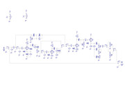
 
I've made the changes for gain compensation in SW3, avoiding pops when switching grids, and relocation of Presence circuit after V2A anode.
Here goes:


Would that be correct?
Cheers
Sono
 
You need a 1Meg grid leak resistor on V1b.
You don't need C21.
You may want to swap C20 and the presence pot, so you don't have high voltage on the pot.
You may need grid stoppers on V1b and V2b.
In general, 1k is a bit low for grid stoppers.
 
Updated schem:


added 10K grid stoppers with a 470pF cap to ground to avoid hiss
added 1M grid leak resistor on V1b
Swapped C20 and the presence pot to avoid high voltage on the pot

I wonder why the original GrindFX schem has C10 and C11 for...


Would changing the 68k input resistor to 33K change something? Gain I suppose?
Do you reckon it's ready to proto? :)

I'm really grateful for your help :)
Cheers
Sono


sonolink said:
added 10K grid stoppers with a 470pF cap to ground to avoid hiss
What hiss? These 470pF will ruin the response, for no sensible gain.

I wonder why the original GrindFX schem has C10 and C11 for...
C10 is necessary for the presence control to work. C11 may be there to isolate DC coming from the outside. Just guessing...


Would changing the 68k input resistor to 33K change something? Gain I suppose?
It would change the input stage's HF response, in an insignificant way.
I think you should melt some solder soon.
 
abbey road d enfer said:
What hiss? These 470pF will ruin the response, for no sensible gain.

When you tell me things I try to learn because I love understanding electronics and many times I'm blind (or severely short sighted), so when you said I needed grid stoppers I searched and read and came across this very interesting paper:

"To find a suitable value for the grid-stopper, simply apply the formula for an RC filter. To get a cut-off frequency of 20kHz we need a grid stopper of: Rg = 1 / (2 pi f C) = 1 / (2 pi × 20000 × 200 × 10^-12) = 39789 ohms
Fender commonly used two jack sockets each connected to 68k grid stoppers which appeard in parallel when using only the 'hi' input, making 34k. Close enough.
However, the input grid stopper adds the most amount of Johnson noise (hiss) of any resistor in the amp. (A 68k stopper generates at least four times more hiss than a typical 12AX7!) Can we use a smaller resistor to reduce noise, but still keep the bandwidth the same? Yes, it's easy. We simply add a little extra capacitance to make up for the lower resistance. I recommend a 10k resistor, which will make the amp much less hissy, together with an extra 100pF to 470pF capacitor from grid to ground."

http://www.valvewizard.co.uk/gridstopper.html

The bit about hiss kinda made sense in my head. I didn't realize that the combination of both components would affect the spectrum.
   
abbey road d enfer said:
C10 is necessary for the presence control to work.
OK, So the if the cap is placed before or after the Presence circuit doens't make a difference except for blocking DC when it's before?

abbey road d enfer said:
C11 may be there to isolate DC coming from the outside. Just guessing...
Wouldn't my modded circuit benefit from that? Or it doesn't really matter or affects tone? Or in other words I'd like to understand why you told me I don't need it :)

BTW, just wondering: aren't R5 and R6 "repeating" R1 and R2 somehow?

abbey road d enfer said:
It would change the input stage's HF response, in an insignificant way.
I think you should melt some solder soon.
I can't wait for it :)
I will do the final corrections, post them and if all is fine, I'll draw the layout :)
 

Latest posts

Back
Top