Help with modifying Circuit please

GroupDIY Audio Forum

Help Support GroupDIY Audio Forum:

This site may earn a commission from merchant affiliate links, including eBay, Amazon, and others.
sonolink said:
"To find a suitable value for the grid-stopper, simply apply the formula for an RC filter. To get a cut-off frequency of 20kHz we need a grid stopper of: Rg = 1 / (2 pi f C) = 1 / (2 pi × 20000 × 200 × 10^-12) = 39789 ohms
Fender commonly used two jack sockets each connected to 68k grid stoppers which appeard in parallel when using only the 'hi' input, making 34k. Close enough.
However, the input grid stopper adds the most amount of Johnson noise (hiss) of any resistor in the amp. (A 68k stopper generates at least four times more hiss than a typical 12AX7!) Can we use a smaller resistor to reduce noise, but still keep the bandwidth the same? Yes, it's easy. We simply add a little extra capacitance to make up for the lower resistance. I recommend a 10k resistor, which will make the amp much less hissy, together with an extra 100pF to 470pF capacitor from grid to ground."
All he says is correct, except he forgets two things:
  • this capacitor loads the input, so the guitar sees too much capacitance, and each subsequent stage sees too much capacitance, which  results in restricted bandwidth.
  •   the grid sees the grid-stopper resistor in series with the output impedance of the preceding stage or the source impedance of the guitar; the main noise contributor is not the grid-stopper, it's the impedance of the preceding stage or the source. 
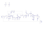
Specifically, if we take the example of V1b, it sees the R14, C14, the 1Meg pot and the output Z of V1a. This results in between 100k and 250k, except when fully CCW. Then you see that whatever the grid-stopper, 10k or 33k, is negligible in terms of noise.
However, in terms of frequency response, the 470pF grid cap is not negligible, creating an HF cut-off at 2.8kHz in the worst case. Cascading this effect in the 4 stages ends up with a cut-off frequency of about 1.7kHz.

    So the if the cap is placed before or after the Presence circuit doens't make a difference except for blocking DC when it's before?
Correct.

C11. Wouldn't my modded circuit benefit from that? Or it doesn't really matter or affects tone? Or in other words I'd like to understand why you told me I don't need it :)
If there is no DC coming from the ouside world, it is not necessary. It may somehow affect the LF response, if driving a low-ish impedance. Don't need is exactly what I mean, whether it's here or not won't change a thing in practice. You know, I could probably add 50 components to your schemo that would not affect tone in any way 8). That's what some so-called gurus do, claiming all sorts of unmeasurable benefits.

BTW, just wondering: aren't R5 and R6 "repeating" R1 and R2 somehow?
I agree, you could dispense with them.

One thing I had not noticed; the input is permanently loaded with the 250k Clean pot. I would probably up it to 500k or even 1Meg. Indeed, C23 & 24 may need to be adjusted accordingly. This is something you'll need to do when tuning the circuit.
 
abbey road d enfer said:
Cascading this effect in the 4 stages ends up with a cut-off frequency of about 1.7kHz.
OUCH!! Not good...  ;D

abbey road d enfer said:
One thing I had not noticed; the input is permanently loaded with the 250k Clean pot. I would probably up it to 500k or even 1Meg. Indeed, C23 & 24 may need to be adjusted accordingly. This is something you'll need to do when tuning the circuit.

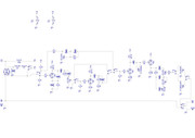
Actually you're right (as usual...). How about this alternative switching to avoid having the input permanently loaded with the 250k Clean pot? I've added R5 between the switch and V1A so that V1A's grid goes to GND when Clean channel is engaged. Does that make any sense? Or is the previous switching scheme preferable?


I'll begin drawing the layout this evening. I can't wait to build this little beast :)
Cheers
Sono
 
sonolink said:
Actually you're right (as usual...). How about this alternative switching to avoid having the input permanently loaded with the 250k Clean pot? I've added R5 between the switch and V1A so that V1A's grid goes to GND when Clean channel is engaged. Does that make any sense? Or is the previous switching scheme preferable?
That is much better.
 
Layout question please: I always place the input grid resistor as close as possible to the grid. In fact I usually solder it directly on the socket. Keeping this in mind, I have drawn the bypass switch I was planning to use into the schem. That led to duplicating the 68K grid resistor and the 1M to GND on the Clean channel so that when it disengages it (the Clean channel), the channel is brought to GND. I hope all that makes sense . Do I actually need R6? Is all this ok or I'm just overdoing things?  :-\


Cheers
Sono
 
sonolink said:
Layout question please: I always place the input grid resistor as close as possible to the grid. In fact I usually solder it directly on the socket.
That is not necessary. The grid-stopper must be close-mounted, but the grid leak can be put almost anywhere, within reason, since its role is conducting DC.

Keeping this in mind, I have drawn the bypass switch I was planning to use into the schem. That led to duplicating the 68K grid resistor and the 1M to GND on the Clean channel so that when it disengages it (the Clean channel), the channel is brought to GND. I hope all that makes sense . Do I actually need R6?
You don't need R6, neither R1, since galvanic continuity is ensured by the 250k pot.
 
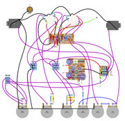
Here's the layout I've come up with:


Under the tubes is the preamp board, and under this are the PSU and the Bypass opto switch. The PSU is fed with a 9V/2A supply.
I will be building this thing these holidays.

To connect this device to a mixer (without using a power amp/speaker) I would have to use a D.I. right?
To get a nice guitar sound I would probably also need to put it through a speaker emulator or an EQ before the D.I. right?

Cheers and Merry Christmas!!
 
One thing that was not obvious on the schemo is that the master pots are in fact a dual type.
First, it is very difficult today to find custom pots.
Second, why the different values?
Third, why not making them separate? that would increase the versatility of the box.
 
abbey road d enfer said:
One thing that was not obvious on the schemo is that the master pots are in fact a dual type.
Quite right. But I have to say it's something I implemented later to avoid redundant pots (please keep reading)

abbey road d enfer said:
First, it is very difficult today to find custom pots.
True. But I've customized them :)
I bought double gang 1M and 100k pots and swapped wipers. It's quite easy to do actually, at least with the brand I got hold of.

abbey road d enfer said:
Second, why the different values?
Third, why not making them separate? that would increase the versatility of the box.
The original circuit ( ), is meant to be used in an amp's FX loop return. According to the designer "If using this effect purely as a stomp-box and not as a pre-amp, then you may wish to substitute the A1M master pot for an A100K. It’ll make it a little less in your face. Or you could just turn it down. Because if you buy an amp later with a loop in it, you might want to run it as a pre into its return."

So in my schemo (actually our schemo, hehe), SW4 is meant as an Output Impedance Switch. When the box is placed in front of an amp it should be operated through the 100K Master Output pot and when placed in an amp's FX loop through the 1M Master Output pot. Since this is a setting that won't be changed while you play, the switch, instead of being a footswitch, will be on the side of the box as a slider. At that point I found myself with 2 Master pots, hence my idea of using a double pot. All this also allows more room for the other pots and boards.
I hope that answers your questions :)
And the next thing I thought about, since many guitarists are more incline nowadays to carry less gear :), was to use the box WITHOUT an amp, directly to a PA or a mixer. I guess one of the outputs or both would work into a D.I. box but I'd probably need to EQ the output to make it sound like a guitar speaker or it'll sound way too fizzy.
If all this is right, a speaker emulator is an EQ or something more is involved?
Cheers
Sono
 
sonolink said:
Quite right. But I have to say it's something I implemented later to avoid redundant pots (please keep reading)
True. But I've customized them :)
I bought double gang 1M and 100k pots and swapped wipers. It's quite easy to do actually, at least with the brand I got hold of.
The original circuit ( ), is meant to be used in an amp's FX loop return. According to the designer "If using this effect purely as a stomp-box and not as a pre-amp, then you may wish to substitute the A1M master pot for an A100K. It’ll make it a little less in your face. Or you could just turn it down. Because if you buy an amp later with a loop in it, you might want to run it as a pre into its return."

So in my schemo (actually our schemo, hehe), SW4 is meant as an Output Impedance Switch. When the box is placed in front of an amp it should be operated through the 100K Master Output pot and when placed in an amp's FX loop through the 1M Master Output pot. Since this is a setting that won't be changed while you play, the switch, instead of being a footswitch, will be on the side of the box as a slider. At that point I found myself with 2 Master pots, hence my idea of using a double pot. All this also allows more room for the other pots and boards.
I hope that answers your questions :)
OK; I just wanted to make sure you have thought about these issues. I see you've covered your bases.

And the next thing I thought about, since many guitarists are more incline nowadays to carry less gear :), was to use the box WITHOUT an amp, directly to a PA or a mixer. I guess one of the outputs or both would work into a D.I. box but I'd probably need to EQ the output to make it sound like a guitar speaker or it'll sound way too fizzy.
If all this is right, a speaker emulator is an EQ or something more is involved?
There's all sorts of speaker emulators, some have just basic EQ, others have some kind of distorsion emulation.
I play quite oten in a place where amps are forbidden. I have tried many speaker/amp emulators. One of the best is the venerable Sans Amp classic (mine is a middle-90's) but I put it out of service because it became unreliable (scratchy pots and switches), I had a Palmer Pocket Amp, which sounded good too, but developed hiss, which made it unusable, and I couldn't fix it, because lack of schemo combined with SMD's. Then I tried a Boss FBM1 that emulates a 59 Bassman, didn't like it, too crunchy for me, then a Boss FDR1, that emulates a Fender Deluxe, I liked it, but found it was too fiddly on stage. For sometime I used a B.......r PB100, which was actually not bad, although iy is just a basic EQ.
Now I use a Line6 Pocket Pod. Considering the price, I think it's a good compromise.
Indeed, if I was very picky, I would use something like a Torpedo or Helix.
For recording, I use DI only for pre-prod, then use an amp to move air. Only once I did use DI, in order to fix a blurred note on a track that had been recorded with a Vox Tonelab. I DI'ed the track clean, and used the convolution tool in Samplitude to impose the same sonic signature.
 
abbey road d enfer said:
OK; I just wanted to make sure you have thought about these issues.
And I thank you for it :)

abbey road d enfer said:
I play quite often in a place where amps are forbidden.
I had no idea you play guitar! That's great to know and I'm glad you do :)

abbey road d enfer said:
There's all sorts of speaker emulators, some have just basic EQ, others have some kind of distorsion emulation.
I play quite oten in a place where amps are forbidden. I have tried many speaker/amp emulators. One of the best is the venerable Sans Amp classic (mine is a middle-90's) but I put it out of service because it became unreliable (scratchy pots and switches), I had a Palmer Pocket Amp, which sounded good too, but developed hiss, which made it unusable, and I couldn't fix it, because lack of schemo combined with SMD's. Then I tried a Boss FBM1 that emulates a 59 Bassman, didn't like it, too crunchy for me, then a Boss FDR1, that emulates a Fender Deluxe, I liked it, but found it was too fiddly on stage. For sometime I used a B.......r PB100, which was actually not bad, although iy is just a basic EQ.
Now I use a Line6 Pocket Pod. Considering the price, I think it's a good compromise.
Indeed, if I was very picky, I would use something like a Torpedo or Helix.
For recording, I use DI only for pre-prod, then use an amp to move air. Only once I did use DI, in order to fix a blurred note on a track that had been recorded with a Vox Tonelab. I DI'ed the track clean, and used the convolution tool in Samplitude to impose the same sonic signature.
Do you reckon the box as it is now would sound ok into a mixer/PA?

Cheers
Sono
 
sonolink said:
I had no idea you play guitar! That's great to know and I'm glad you do :)
You'd be shocked learning that several of us who are posing as respectable members of society are in fact busying themselves with the task of killing the hair cells in their fellow citizens' organ of Corti.  8)

Do you reckon the box as it is now would sound ok into a mixer/PA?
You may have to do some adjustment on the voicing, but I think you can find a satisfoctory setting.
 
abbey road d enfer said:
You'd be shocked learning that several of us who are posing as respectable members of society are in fact busying themselves with the task of killing the hair cells in their fellow citizens' organ of Corti.  8)
All the more respectable to me you guys are 8) A world with more music and true Rock'n'Roll would indeed be a better one  ;)

abbey road d enfer said:
You may have to do some adjustment on the voicing, but I think you can find a satisfoctory setting.
You mean adjusting the caps and resistor values in the tone stack?

Merry Christmas and thanks again for your help :)
Cheers
Sono
 
sonolink said:
You mean adjusting the caps and resistor values in the tone stack?
Not only in the tone stack; you may want to alter C10, R14 & C14, R17 & C16, R24 and C3 & C24, they all shape the response.
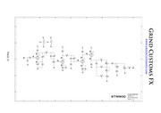
BTW, I just noticed the presence control is not correct. Check attachment for correct connection.
 

Attachments

  • correct.jpg
    correct.jpg
    193.6 KB · Views: 5
abbey road d enfer said:
BTW, I just noticed the presence control is not correct. Check attachment for correct connection.
Oh thanks for checking that :)

abbey road d enfer said:
Not only in the tone stack; you may want to alter C10, R14 & C14, R17 & C16, R24 and C3 & C24, they all shape the response.
Ok. I should probably first build it and hear what it sounds like on an amp and then try the D.I. thing and go from there.
Cheers
Sono

 
Is the value of C10 (0.68uF) critical? Is it ok to replace it with a 1uF/50v electrolytic? I'm asking because the 0.68uF film caps I have are 250VDC and a bit bulky...

Cheers
Sono
 
sonolink said:
Is the value of C10 (0.68uF) critical? Is it ok to replace it with a 1uF/50v electrolytic? I'm asking because the 0.68uF film caps I have are 250VDC and a bit bulky...
Indeed you can; however electrolytic caps have a larger tolerance than film, and their value drifts with age. It may probably not matter much.
 

Latest posts

Back
Top