DIY Alembic F2B preamp clone hum noise

GroupDIY Audio Forum

Help Support GroupDIY Audio Forum:

This site may earn a commission from merchant affiliate links, including eBay, Amazon, and others.

weiss

Well-known member
Joined
Jun 16, 2014
Messages
1,436
Location
Germany
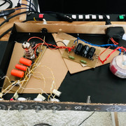
hey guys, just finished one channel of the alembic preamp clone i made.
I experience some heavy hum around 50, 150, 250 and 350Hz. Any idea how i could eliminate this?

Looks like mains hum to me - the toroid is not mounted to the chassis at the moment but will this fix it?
Any other ideas for improvement?

thanks

Ansgar

 
Any links to drawing you are using????

In addition to what Rob said, (is there a heater center tap on that??? Maybe make one if not) ,  are those ac heaters???? if so, that audio line laying right on the ac line usually isn't the best......??

not sure what the deal is with your grounds either???
 
Hey guys, thanks for your help.


I used minus (-) from power supply as central ground (see schematic)


Attachments

  • IMG_3285.jpg
    IMG_3285.jpg
    733 KB · Views: 46
scott2000 said:
Any links to drawing you are using????

In addition to what Rob said, (is there a heater center tap on that??? Maybe make one if not) ,  are those ac heaters???? if so, that audio line laying right on the ac line usually isn't the best......??

not sure what the deal is with your grounds either???

Yes, these are ac heaters, you are right, that needs to change... thanks
i used this schematic, am i missing something?

i added 2k2 resistors to decouple channels. I left out the brite switch, no need.
 

Attachments

  • IMG_3286.jpg
    IMG_3286.jpg
    732.9 KB · Views: 29
weiss said:
Yes, these are ac heaters, you are right, that needs to change... thanks
i used this schematic, am i missing something?

i added 2k2 resistors to decouple channels. I left out the brite switch, no need.


looks ok to me...... AC heaters are fine usually but you really need to be tidy in your layout/wiring....... elevation works well too..... I think one of Gyraf's units has a nice application of this but I can't remember which one.....

The grounding scheme is important too in regards to your layout..... not sure how all of that is set up yet???

I'll keep staring.....

Never thought about using cardboard.....pretty cool....

 
1. Keep the heater wires away from anything around the input (R1, R2, C1 and R3). Most hum in a correctly wired tube amp is going to come from the magnetic fields given off by the relatively high current of the heater wires which can be coupled into the high impedance high gain circuitry of the input and amplified. So you want to run the two wires close to one another so that the fields cancel each other out. This is why they are usually gently twisted together. If the twist is not close at the end and is laying on top of input circuitry (like R1, R2, R3 C1), it will induce hum on the input which will be amplified.

2. Use a separate ground for the stuff connected to the input (R2 and C1 in particular) and run that wire back to the filter caps of the supply. If the high impedance high gain input is connected to the end of several other stages that are dumping a lot of current into the ground, because a wire itself has a small resistance and inductance, it will develop "noise" that can then make a positive feedback loop.

3. Make sure your 1/4" plug is grounded to the metal enclosed chassis. If you're testing, use a separate wire to act as the chassis and run it back to the earth of the mains plug (which is then connected to the ground at the filter caps of the supply.

4. Any high impedance high gain inputs should be fed with a well shielded cable and generally minimize unshielded runs (so put R1 right next to the tube grid) but only ground the shield at the chassis end. High impedance high gain inputs are going to amplify any noise induced in the exposed wires just as well as the intended signal so protect the inputs.
 
weiss said:
Hey guys, thanks for your help.
I used minus (-) from power supply as central ground (see schematic)

Zentraler massepunkt should be placed at the output of capacitors bank at crossed GND1 and 2.
 
scott2000 said:
looks ok to me...... AC heaters are fine usually but you really need to be tidy in your layout/wiring....... elevation works well too..... I think one of Gyraf's units has a nice application of this but I can't remember which one.....

The grounding scheme is important too in regards to your layout..... not sure how all of that is set up yet???

I'll keep staring.....

Never thought about using cardboard.....pretty cool....

yeah, i like to do it that way to test everything.  :)

squarewave said:
1. Keep the heater wires away from anything around the input (R1, R2, C1 and R3). Most hum in a correctly wired tube amp is going to come from the magnetic fields given off by the relatively high current of the heater wires which can be coupled into the high impedance high gain circuitry of the input and amplified. So you want to run the two wires close to one another so that the fields cancel each other out. This is why they are usually gently twisted together. If the twist is not close at the end and is laying on top of input circuitry (like R1, R2, R3 C1), it will induce hum on the input which will be amplified.

2. Use a separate ground for the stuff connected to the input (R2 and C1 in particular) and run that wire back to the filter caps of the supply. If the high impedance high gain input is connected to the end of several other stages that are dumping a lot of current into the ground, because a wire itself has a small resistance and inductance, it will develop "noise" that can then make a positive feedback loop.

3. Make sure your 1/4" plug is grounded to the metal enclosed chassis. If you're testing, use a separate wire to act as the chassis and run it back to the earth of the mains plug (which is then connected to the ground at the filter caps of the supply.

4. Any high impedance high gain inputs should be fed with a well shielded cable and generally minimize unshielded runs (so put R1 right next to the tube grid) but only ground the shield at the chassis end. High impedance high gain inputs are going to amplify any noise induced in the exposed wires just as well as the intended signal so protect the inputs.

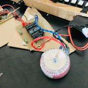
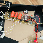
I'm gonna keep the wires seperated and use another ground for the input. I didn't connect the jacks yet, sure that was my fault.
thanks for your help and thoughts, squarewave !!  :)

moamps said:
Zentraler massepunkt should be placed at the output of capacitors bank at crossed GND1 and 2.

what do you mean? what should i change exactly??
 
weiss said:
is there any downside?

Not really, but take look at the Telefunken V76 mic amp, they're pretty sensitive & they don't have d.c heaters & they don't hum unless something is wrong with them.  Or old valve radios generally don't have d.c heaters.  You can experiment &make your own choice, do what floats your boat.
 

Latest posts

Back
Top