Miller capacitance at valve input

GroupDIY Audio Forum

Help Support GroupDIY Audio Forum:

This site may earn a commission from merchant affiliate links, including eBay, Amazon, and others.

untune

Well-known member
Joined
Oct 28, 2016
Messages
228
Location
Manchester, UK
Hi all..

I started a preamp project a while back, I'm currently trying to finish it off and build a case for it and I'm going over the design to see what I might be able to improve.

So the second channel is intended to be an instrument amp for bass guitar, straight into a triode connected 6au6. It has more than enough gain but I was curious about the grid stopper, and I chose a 1k2 resistor (can't remember why, likely naively borrowed from another design).  Going off bass/guitar inputs this seems a small value. Calculating the miller capacitance for a triode 6au6 I get around 68pF give or take.  Combined with the stopper that should give me a LPF with a cutoff of almost 200kHz if I've worked it out right. Seems extremely high.

Calculations again suggested than my ideal grid stopper would be around 120k, which I guess would add too much noise.

An example I read using a 12ax7 (which has a miller capacitance of approx 192pF) suggested the solution would be to pair a 10k resistor and a small cap of 100-470pF before the input to lower noise and create a more fitting low pass filter for input RF interference.

I applied the same logic to my 1k2 and worked out I'd need a cap of about 3000pF to 5600pF for a reasonable filter cutoff.

I expect that there's a disadvantage to having additional capacitance there and I'm curious what the ideal tradeoff is in terms of which component values to choose here. Are there any rules to follow?

Cheers!
 
untune said:
Calculating the miller capacitance for a triode 6au6 I get around 68pF give or take. 
Unless you have some gain degeneration or a very low plate resistor, the Miller cap should be close to 100pF. Not a very significant difference anyway.

Combined with the stopper that should give me a LPF with a cutoff of almost 200kHz if I've worked it out right. Seems extremely high.
Indeed, but if it's the input stage, the source impedance should be dominant over the grid stopper. Typically a passive electric guitar would show a complex impedance, but almost always higher than 50 kohms.

Calculations again suggested than my ideal grid stopper would be around 120k, which I guess would add too much noise.
That would be for a 20kHz BW, which you actually don't need for guitar. The impact on input noise is hard to tell since there are no noise data for the 6AU6, being an RF tube. I would think, in conjunction with teh source impedance, that would result in about 8-10kHz BW, which is perfectly suitable for guitar.
Anyway, there is no use for such a drastic filtering, since it is done for shunting to ground RF interference and possible capacitive coupling with other stages.

An example I read using a 12ax7 (which has a miller capacitance of approx 192pF) suggested the solution would be to pair a 10k resistor and a small cap of 100-470pF before the input to lower noise and create a more fitting low pass filter for input RF interference.

I applied the same logic to my 1k2 and worked out I'd need a cap of about 3000pF to 5600pF for a reasonable filter cutoff.
You can't do that, because this capacitor loads the source. Depending on the position of the controls and the type of p/u's, that could shift the resonance by more than a factor two (i.e. one octave down) and make the response muffled.

I expect that there's a disadvantage to having additional capacitance there and I'm curious what the ideal tradeoff is in terms of which component values to choose here. Are there any rules to follow?
Yes. You must consider the input stage in conjunction with the source, which includes the cable (about 700pF for a 5 meter cable). Worst case, a humbucker-equipped gtr  shows 125kohms. Seeing only the cable, it results in a BW of only 2kHz!
That may be surprizing, but that's what we've been conditioned to accept as a normal jazz guitar sound, and that's why rock relies on distortion and grit to enhance the treble content.
Adding 3 nF would result in a BW of about 200 Hz, which, by all acoounts, is questionable.
 
abbey road d enfer said:
Unless you have some gain degeneration or a very low plate resistor, the Miller cap should be close to 100pF. Not a very significant difference anyway.
Indeed, but if it's the input stage, the source impedance should be dominant over the grid stopper. Typically a passive electric guitar would show a complex impedance, but almost always higher than 50 kohms.
If the OP is talking about bass guitar, I always thought those pickups were somewhat lower impedance than lead guitar (maybe more like 10k ohm)

JR

[caveat I am not the tube guy here }
That would be for a 20kHz BW, which you actually don't need for guitar. The impact on input noise is hard to tell since there are no noise data for the 6AU6, being an RF tube. I would think, in conjunction with teh source impedance, that would result in about 8-10kHz BW, which is perfectly suitable for guitar.
Anyway, there is no use for such a drastic filtering, since it is done for shunting to ground RF interference and possible capacitive coupling with other stages.
You can't do that, because this capacitor loads the source. Depending on the position of the controls and the type of p/u's, that could shift the resonance by more than a factor two (i.e. one octave down) and make the response muffled.
Yes. You must consider the input stage in conjunction with the source, which includes the cable (about 700pF for a 5 meter cable). Worst case, a humbucker-equipped gtr  shows 125kohms. Seeing only the cable, it results in a BW of only 2kHz!
That may be surprizing, but that's what we've been conditioned to accept as a normal jazz guitar sound, and that's why rock relies on distortion and grit to enhance the treble content.
Adding 3 nF would result in a BW of about 200 Hz, which, by all acoounts, is questionable.
 
JohnRoberts said:
If the OP is talking about bass guitar, I always thought those pickups were somewhat lower impedance than lead guitar (maybe more like 10k ohm)

JR

[caveat I am not the tube guy here }
Naah, they are fitted with 250 or 500k pots and the p/u inductance is about the same (sometimes much higher). 10k would be the DCR of a Gibson EB1, inductance 12-15H!
OTOH there are more active basses than active electric guitars.
BTW, today, expectations in terms of HF extension are more demanding for bass than for guitar.
Trunking the response at about 4kHz for guitar is standard for smoothing distortion; OTOH bass players now use full-range rigs with HF horns for letting out their frustration of not being guitar heroes.  ;)
 
Thanks for the input! Apologies if I skimmed over details - I wrote this while standing uncomfortably on a train to Leeds this morning  :-\

abbey road's explanations have clarified things, thanks for that.  I was just crunching numbers out of curiosity - but yes, main use is indeed passive bass guitar (guitar hero wannabe, eh :p ) and aside from a Precision, my main bass uses a custom wound pickup that's probably akin to a Thunderbird.  But I do also like to run synthesizers through it and having the full spectrum is much more important in that case.  Also this pre outputs a line level signal for recording - it doesn't drive a speaker.

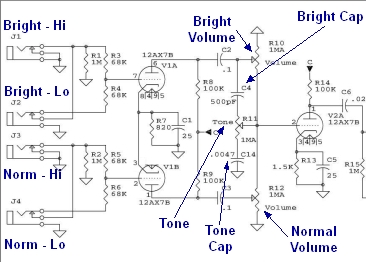
The reason I was revisiting this part of the design is because the front panel I am using has space for two jacks, and I'm currently only utilising one.  My thinking was it would make sense to wire both in a switching configuration to give me a Hi/Lo input as is often seen on instrument amps, just to give me an option for taming a bigger signal from either active instruments or synths etc.

The example I was looking at says: 'Fender commonly used two jack sockets each connected to 68k grid stoppers which appeared in parallel when using only the 'hi' input, making 34k' and I was trying to work out what kind of values I'd need to be using in my case, ie into a 6AU6 triode as opposed to an ECC83.  Grid leak on the input is 500k and I wonder if it should be at least 1meg - again it was a couple of years ago so I forget exactly why I settled on this value.  For what it's worth it sounds really good to my ears ;D
 
untune said:
my main bass uses a custom wound pickup that's probably akin to a Thunderbird. 
With about 12kohm DCR, their inductance is bound to be quite high, probably about 10H, so their impedance is about 100kohms at 1kHz.

The reason I was revisiting this part of the design is because the front panel I am using has space for two jacks, and I'm currently only utilising one.  My thinking was it would make sense to wire both in a switching configuration to give me a Hi/Lo input as is often seen on instrument amps, just to give me an option for taming a bigger signal from either active instruments or synths etc.
Just make sure you do it the Fender way, where using input 1 gives 1Megohm input impedance, while input 2 is about 130k.

I was trying to work out what kind of values I'd need to be using in my case, ie into a 6AU6 triode as opposed to an ECC83.  Grid leak on the input is 500k and I wonder if it should be at least 1meg -
That may be an issue. 6AU6 seems to have a rather high grid current (0.5uA?), so even 500k is enough to shift significantly the op point. You'll probably need to adjust the cathode resistor and make sure the grid is DC-decoupled from the input with a capacitor.
 
6AU6 can have quite low grid current. 1Meg should be fine.

> grid stopper, and I chose a 1k2 ... miller capacitance for a triode 6au6 I get around 68pF give or take.

Draw the WHOLE circuit!!

The 1.2k is in-series with the 5K-500K of the instrument. Practically negligible.

The 68pFd is nearly parallel with the instrument CORD, say 30pFd/foot, is usually *hundreds* of pFd. So another 68 is nothing. FWIW a 12AX7 input is liable to be 100pFd.

60+ years of accumulated experience has given us instruments that WORK with such values. (Have worked great since the 1950s.) Guitar pickup makers push the limits, winding-up more turns for stronger midrange at the "loss" of a quicker sharper high-cut in the 2KHz-5KHz range. This too is part of the plan. The higher harmonics of naked steel strings are ugly. We want to be cutting past ~~3KHz more-or-less.

For general use, steal Fender's input structures. They work. 1Meg leak, 34K stopper, and ~~100pFd gives light loading of the treble resonance and a 40KHz roll-off so the AM broadcast band is down 25dB, less likely to break-through the grid diode and put football on top of your solo.
 
Thanks for all the input, apologies for the delay.

It's making sense now... plus I appear to have miscalculated; I found a Brimar spec sheet with different values for a triode 6AU6 that make the calculated miller capacitance closer to 150pF.  Recalculating gives an 'ideal' resistance of closer to 50k as opposed to 120k.  So, given the info that has been provided, I'm sure it will make little difference and as PRR says the Fender values will probably work fine.  I've seen Ampeg B15 schematics with parallelled 120K resistors, and 100K/47K and nobody was complaining about the tone there.

I might grab a few different pairs of values and try them out.  One other aside- metal film or carbon comp, will it make a big difference here?  I've read carbon comp is preferred but modern metal films won't really be an issue
 
untune said:
One other aside- metal film or carbon comp, will it make a big difference here?  I've read carbon comp is preferred but modern metal films won't really be an issue
It's irrelevant for grid leak and grid-stopper. The main difference between carbon comp and carbon film is their propensity to generate noise and distortion when submitted to current, carbon comp being worst. It seems some prefer their amps noisier and grittier...
Since there is no current to speak of in the grid circuit, it makes no difference. However, carbon film are more stable than carbon comp and about 10x less costly.
 
Thanks for the additional info; I wired everything up yesterday using the standard hi/lo wiring that you'll find with a quick search.

I'm getting no signal whatsoever and I've double and triple checked the wiring and everything seems solid. The only thing I can think that might be screwy is that I've used a screened two core twisted cable (ie low capacitance balanced cable) to send the signal from each jack to the paralleled grid stoppers, sharing a common shield. Is there a possibility that this will cancel the signal out, being twisted together?

When I was using the old 1k2 stopper, I was using one of the two cores for the signal, and the other core was connected to the shield at the jack side, and at the valve side I had the outer shield snipped with the 'shield' core grounded at the valve. Had no problems with that
 
Hi Scott

See the link, ignoring the two on the left - I just have the 'normal'hi and lo

https://robrobinette.com/images/Guitar/HowAmpsWork/Fender_Input_Jacks_3.png

So where you see a wire going from tip of jack one, and a wire going from tip of jack two going to their respective 68k resistors - imagine those two wires are the two cores you would find inside a balanced two conductor cable, sharing a common shield which is attached to ground at the jack and also at the valve base.
 
LOL...Sorry, getting over a cold and can't "imagine" too well this minute....

Confused by saying ignore left image but mentioning jack one??? Do you mean jacks 3 and 4??

When you say valve base, what does this mean???? I'm guessing  cathode resistor ground????
nevermind....guess you mean the actual base ground???

Darn cold..... I'll keep staring....

 
No problem! It's that time of year, hope you feel better soon :D

Yes sorry I didn't notice the jacks were numbered - I have 3 and 4

Yes that's right - to clarify there's a centre pin on the valve base which is just a local ground point which connects up to the cathode resistor ground
 
It looks a little different drawn that way but I believe that's it - only difference with mine I see is that I have linked the grounds for both jacks together rather than just grounding 1 at the base of the 1meg resistor
 
sorry, I erased the post....I think it was the wrong one.....

I think this may be it...???

Fender_Input_Jacks_0.jpg


There has to be some wiring error somewhere..... not sure about the twisted pair causing an issue though.....never heard of that....
 
untune said:
I'm getting no signal whatsoever and I've double and triple checked the wiring and everything seems solid. The only thing I can think that might be screwy is that I've used a screened two core twisted cable (ie low capacitance balanced cable) to send the signal from each jack to the paralleled grid stoppers, sharing a common shield. Is there a possibility that this will cancel the signal out, being twisted together?
Impossible. I'm pretty certain your screened cable is shorted somewhere.
 
abbey road d enfer said:
Impossible. I'm pretty certain your screened cable is shorted somewhere.

Inclined to agree; all I can think is that I've nicked the wire while stripping it back, I've made a replacement and will test it tomorrow
 

Latest posts

Back
Top