LTSpice: CFP Mic Pre w/ Filtering

GroupDIY Audio Forum

Help Support GroupDIY Audio Forum:

This site may earn a commission from merchant affiliate links, including eBay, Amazon, and others.

Bo Deadly

Well-known member
Joined
Dec 22, 2015
Messages
3,266
Location
New Jersey, USA
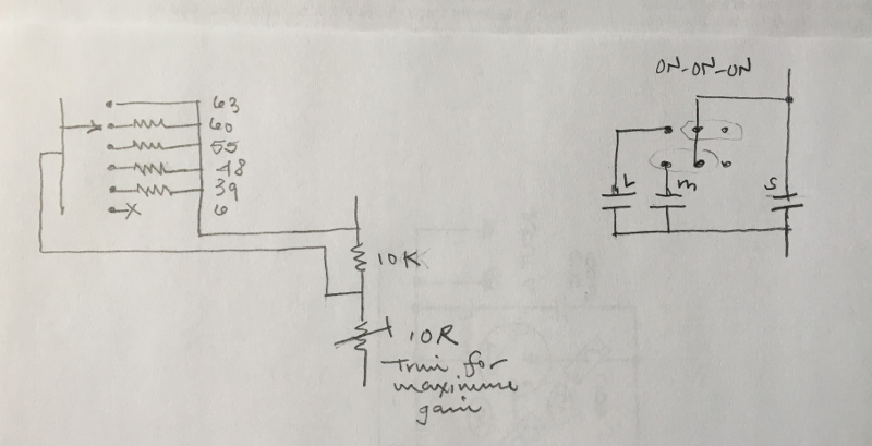
Is it possible to use a smaller cap in the gain control to low-cut in a Complementary Feedback Pair circuit?

Here's my simplified circuit (model attached renamed .asc to .txt):

Cfp1.png


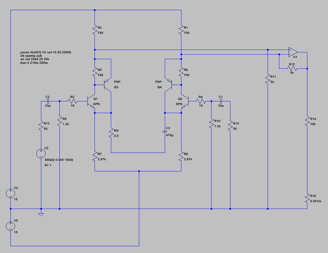
The THAT datasheets recommend large caps like 3300u with low values of Rg so as not to loose low frequencies. But simulations suggest that 470u is suitable with the smallests values of Rg.

My immediate though is that distortion would be an issue with an electrolytic. To get to 200Hz would require ~150uF. Would a tantalum work?

Also, is the noise gain a concern here?
 

Attachments

  • Cfp1.txt
    4 KB · Views: 12
ruffrecords said:
One problem is that the -3dB point varies with Rg.
Yeah, but in a way it's sort of a "feature". At higher gain, there is more noise and less headroom. So by reducing low frequencies as gain is increased, the chances of clipping are reduced and SNR improves which generally makes the whole thing more forgiving to level settings.

This is for a simple small "floor box" pre BTW. Lots of gain. Low noise. Probably one knob.
 
As I understand this would not filter/cut, just reduce preamp gain below Fc
That would be kind of unorthodox, but could be useful...
A method like that is often used in guitar boosters
 
L´Andratté said:
As I understand this would not filter/cut, just reduce preamp gain below Fc
That would be kind of unorthodox, but could be useful...
A method like that is often used in guitar boosters
Yeah, I guess it is similar to bypassing the cathode resistor in a tube amp. At least in behavior.

The important thing is noise and distortion. Because that network is integral to the 60dB+ gain of the circuit, any noise or distortion is going to be exacerbated. The noise simulation shows noise goes down accordingly. So apparently the noise gain is not higher like it would be in an inverting op amp stage. As for distortion, I just need to find the right set of caps. I was reading a thread here regarding using two anti-parallel electrolytic caps to cancel harmonics.

If it works and noise in the pass band is not more than it would be with the full-sized cap AND distortion at Fc is not intolerable, then integrating the low cut right at the input where most of the gain is will increase dynamic range and SNR.

Yes, Fc will shift up as gain is increased. But in a way, that's nice because as you increase gain, the risk of clipping does NOT increase by an equal amount. So it's more forgiving. However, I accept that there needs to be a way to adjust Fc independent of gain.

Again, this is supposed to be super simple but now I'm thinking about two controls like this:

IMG_3502.png


These represent Rg and Cg in the CFP gain control network. The 3 postion ON-ON-ON toggle would make parallel caps S|M|L left, S|M center and S when switched right. So as you switch to the left, Fc shifts down, to the right Fc shifts up.
 
squarewave said:
My immediate though is that distortion would be an issue with an electrolytic.
Yes, it's the main reason for overdimensioning the cap. LF response is the easy explanation.

Would a tantalum work?
You would need to use two tants back-to-back, and even then be worrying about them going shorted because of reverse polarity.
 
abbey road d enfer said:
Isn't it already the case? And how differently would you do that?  ???


R12 seems to be the feedback resistor, I would close the loop through the transistors a la Double balanced pre, but im just sayin, it doesnt look like the cfp is in the feedback path of the opamp to me.
 
user 37518 said:
R12 seems to be the feedback resistor, I would close the loop through the transistors a la Double balanced pre, but im just sayin, it doesnt look like the cfp is in the feedback path of the opamp to me.
You're correct, I didn't look at the schemo. Refernce to a THAT circuit made me think voltage NFB would be applied, but here it's just current NFB.
The distorsion mechanism due to capacitor non-linearities is the same in both cases, though.
 
Hmm, according to my cheap cap / inductance meter thing, the ESR of the tantalums that I have is actually pretty high (10u 800 mOhms) compared to even regular electrolytics (22u 200 mOhms). Apparently tantalums and even low ESR or tantalum polymer capacitors are only low ESR at high frequencies (100kHz).

Maybe I should just try the lowest ESR bi-polar electrolytic I can find. Unfortunately ESR is not something usually published in datasheets for electrolytics. But they do list ripple current. Is it reasonable to assume that the higher the ripple current, the lower the ESR?
 
squarewave said:
Hmm, according to my cheap cap / inductance meter thing, the ESR of the tantalums that I have is actually pretty high (10u 800 mOhms) compared to even regular electrolytics (22u 200 mOhms). Apparently tantalums and even low ESR or tantalum polymer capacitors are only low ESR at high frequencies (100kHz).
Your measurements are not wrong - solid tantalum caps have a relatively high ESR, something that was exploited by a number of 3 terminal regulators in order to stabilize their feedback loop. Modern MLCCs and aluminum electrolytics will de-stabilize those regulators, since their ESR is too low. Solid Ta caps are made from a sintered mass of tantalum spheres, onto which tantalum pentoxide dielectric has been grown, so their resistance is distributed throughout the tiny points of contact within the sintered tantalum bead. This makes the overall cap not all that resonant, since the impedance is evenly distributed, along with the bulk capacitance and inductance. But, the ESR ends up being very high, especially compared to modern aluminum electrolytics and multi-layer ceramics.

The ESR of a solid Ta cap isn't actually low at HF, but rather its self resonance is heavily damped - the net impedance of the cap around resonance is swamped by the high ESR, making the self resonance region a broad, shallow impedance 'trough', and not a sharp impedance null like you'd find with a low impedance cap. This makes it a good bypass cap, since it will not ring when you apply transients to it - the impedance around its resonant frequency is very heavily damped, unlike modern low ESR caps which show a definite impedance null at resonance.

Maybe I should just try the lowest ESR bi-polar electrolytic I can find. Unfortunately ESR is not something usually published in datasheets for electrolytics. But they do list ripple current. Is it reasonable to assume that the higher the ripple current, the lower the ESR?
Again, you're right on target. The ripple current rating is sometimes calculated as the current needed to generate a specific temperature rise, given the capacitor's ESR. So yes, a lower ESR will allow a greater ripple current given a specific value of temperature rise.
 
When judging ESR based on ripple current, should I consider that as a function of voltage rating?

Consider two capacitors that are the same model and size but different voltage rating and thus different ripple current:

Nichicon UVP0J101 100u 6.3V -- 125mA ripple
Nichicon UVP2A101 100u 100V -- 425mA ripple

At first glance this would suggest that going with the higher voltage part would have lower ESR. But maybe not. If the ripple current is a function of voltage then maybe it would be more accurate to compare values computed using ohms law like:

6.3 / 0.125 = 50.4
100 / 0.425 = 235

in which case maybe the lower voltage part is actually lower ESR?

Although the loss tangent values are lower with higher voltage rating.
 
Ripple current is more of an allowable  spec,  think of it in terms of i^2 x r power dissipation.  More allowable ripple current implies the esr is lower, so there is not excess power dissipation causing excess temperature rise.
 
john12ax7 said:
Ripple current is more of an allowable  spec,  think of it in terms of i^2 x r power dissipation.  More allowable ripple current implies the esr is lower, so there is not excess power dissipation causing excess temperature rise.
That seems to be consensus within capacitor manufacturers. It has to be put in regard with the size of the capacitor, though, since a physically larger capacitor would tolerate larger heat dissipation.
 
abbey road d enfer said:
That seems to be consensus within capacitor manufacturers. It has to be put in regard with the size of the capacitor, though, since a physically larger capacitor would tolerate larger heat dissipation.

Doesn't the rating include the package? My understanding was it is the rating for the actual physical part. So it's not the best way to determine esr,  but a good proxy in lieu of better data.
 
john12ax7 said:
Doesn't the rating include the package? My understanding was it is the rating for the actual physical part.
Indeed.

So it's not the best way to determine esr,  but a good proxy in lieu of better data.
I think I didn't make myself clear.
Hypothetically, there could be a capacitor of size X with Y ripple current rating, that would compute to Z ESR.
And another of size 4X with ripple current 2Y, that would also result in the same Z ESR.
My conclusion is that a better ripple current alone does not guarantee a better ESR.
 

Latest posts

Back
Top