Boss flipflop for nonlatching pushbutton

GroupDIY Audio Forum

Help Support GroupDIY Audio Forum:

This site may earn a commission from merchant affiliate links, including eBay, Amazon, and others.

boji

Well-known member
Joined
Jan 6, 2010
Messages
2,376
Location
Maryland, USA
Howdy,

Last night I ran across a simple toggle circuit from a Boss pedal that PRR shared some time ago. I can't seem to locate the thread today.
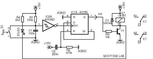
Might anyone know the one I'm talking about? I think uses two transistors instead of a cmos  & Schmidt like the one below.
moNx9ka.jpg


Additionally, I'm curious to know if you have a favorite circuit for switching with non-latching push buttons, and why.  For my needs, it should pull a CV to ground to un-energize a separate dual relay circuit which includes debouncing.
Thank you!

Edit:  I may try out the one below if the boss one can't be recalled:
5dbWTGJ.gif


You can find the Boss circuit on any of their schematics, see here.


> Additionally, I'm curious to know if you have a favorite circuit for switching with non-latching push buttons, and why


Microcontroller. Minimum parts count, debouncing in software, you can even check for zero crossings and only switch then to suppress any noise.
 
I've used many D-type FF (like 4013) to latch switches but they can involve timing considerations, to avoid switch bounce issues.

+1 to micro... maybe do the whole design with a micro.  ;D

JR
 
I know the thought of writing code for a microcontroller is painful for a lot of folks but it really is so much better if you take the time to learn it.

Just to give you an idea of what the code could look like, here's a fragment of Arduino code from my Neve channel strip:

Code:
....
case TACT_NEVE_LOZ:
    if (d->state == DEBNC_ST_RELEASE) {
        BIT_FLIP(st->tact_led, LED_NEVE_LOZ);
        if (spgain.step < 13) { 
            BIT_FLIP(st->rly_iox_curr, RLY_IOX_LLOZ);
        } else {
            BIT_FLIP(st->rly_iox_curr, RLY_IOX_MLOZ);
        }
        l9823_write(PIN_IOX_L9823_CS, st->rly_iox_curr);
    }       
    break;
case TACT_LA3A_VU:
    ...
This code fragment is from a "switch" statement that would be called with the id of a button. In this "case" the button is the "Low Z" button that toggles the relay that changes the transformer primary between series and parallel. It first checks to see if the debouncing code (which I called "debnc" for short) state indicates that the button was released [1]. If it is, it flips the bit for the LED above the button (the LED driver is written once later in the loop). Then it checks to see what the gain step is because if the gain knob is positioned for line input vs mic input then it needs to toggle a different relay (I have both line and mic input so the "Low Z" button works for both). So I flip the bit for the right relay and then write that change to the relay driver (the STMicroelectronics L9823).

So with 10 lines of code I handled some fairly complex tasks.

Now think about the circuitry required to do the same thing.

[1] The button is checked for release as opposed to pressed because if the Low Z button is pressed and held for a short time the unit enters a "programming mode". So I had to check if the button was released instead of just pressed. The other button functions are activated when pressed. All release events other than for the Low Z button are ignored.
 
You can find the Boss circuit on any of their schematics
Ah cool, thanks Volker!

Microcontroller. Minimum parts count, debouncing in software, you can even check for zero crossings and only switch then to suppress any noise.

+1 to micro... maybe do the whole design with a micro.  ;D

Heh ok ok... I was trying to avoid yet another amtel in the rack.  ::)

Looking for small mc's, an arduino micro is probably too big and would be overkill on each PCB, since I only have one pushbutton per group card (8 total) that needs latch logic.
iNP0CSC.jpg


I guess I could work with what I know and add an Arduino Uno to the rack of Mega's I'm already using for Solo/Mute logic, and break it out to the single pushbutton and corresponding relay pair inside each of the eight group ACA cards...

I have yet to explore the use of 8pin dip micros.

Any suggestions for a super tiny format for a relative beginner? I'm really only comfortable using the Arduino IDE and usb upload procedure at this point.
 
I know the thought of writing code for a microcontroller is painful for a lot of folks

Oops I was writing my post and missed yours Square.  Yes, it has been a painful journey but entirely rewarding.
I took a brute-force approach as I've not tried my hand at shift registers or multiplexing. 
MOJxOyj.jpg


I guess the reason for wanting to play with a few transistors is it would avoid digital signal wires floating around my card's internals (yes this is probably an irrational fear if grounding layout is solid). As is, the mute solo buttons and relay cv's are at the edge of the input channels, well away from audio signal, and controllers are under the console.  But this particular button (group card input assign) would be in the middle of the PCB and close to opamps.

 
This code fragment is from a "switch" statement that would be called with the id of a button. In this "case" the button is the "Low Z" button that toggles the relay that changes the transformer primary between series and parallel. It first checks to see if the debouncing code (which I called "debnc" for short) state indicates that the button was released [1]. If it is, it flips the bit for the LED above the button (the LED driver is written once later in the loop). Then it checks to see what the gain step is because if the gain knob is positioned for line input vs mic input then it needs to toggle a different relay (I have both line and mic input so the "Low Z" button works for both). So I flip the bit for the right relay and then write that change to the relay driver (the STMicroelectronics L9823).

So with 10 lines of code I handled some fairly complex tasks.

Now think about the circuitry required to do the same thing.

[1] The button is checked for release as opposed to pressed because if the Low Z button is pressed and held for a short time the unit enters a "programming mode". So I had to check if the button was released instead of just pressed. The other button functions are activated when pressed. All release events other than for the Low Z button are ignored.

Wow you got some cool logic going on there. Care to share a picture? When you say series /parallel are you changing the output ratio or just the z input?
 
boji said:
Wow you got some cool logic going on there. Care to share a picture? When you say series /parallel are you changing the output ratio or just the z input?

Yeah here:
cs2.gif


The "Low Z" control is just like "Lo Z" button on an old Neve but with a relay. It switches the input transformer split primary between series and parallel which gives you either 1:2 or 1:4 respectively for the mic transformer (VTB9045) and for the line transformer (VTB9046) it switches between 2:1 and 1:1 I think.

Regarding using microcontrollers, I was not suggesting that you use more than one. One Arduino Micro is more than powerful enough for an entire console. What you would need are IO expanders that daisy chain. Then you can use one chip select to write whatever number of bytes of data to a chain of IO expanders that are in turn driving chip selects for LED and relay drivers and doing input for momentary switches. That leaves 12 analog inputs for reading levels although I don't know if the ADC can accurately read all 12. I have only used 2 simultaneously no problem.

So I would definitely not use more than one micro. It would actually make things harder I think because they would not be coordinated. If you provide a basic list of the numbers of relays, leds (individual and VU meters) and momentaries, I could give you a breakdown of how to drive / read them all from one micro.

Regarding digital noise, I have done very careful measurements and found that it is completely non-existent. However, I have another API style channel strip that has LED lines for the VU meter within a few millimeters of the gain pot and I can measure noise. But in the Neve channel it's absolutely not an issue so it can be done. You just have to be careful about routing. I also use 3 separate grounds one of which is just for digital, relays and led drivers.
 
Thanks for the picts! I really like how you incorporated different building blocks and stacked pcb's like they do with modular synths to keep it 1u. That's some sweet diy right there.

If you provide a basic list of the numbers of relays, leds (individual and VU meters) and momentaries, I could give you a breakdown of how to drive / read them all from one micro.
  Wow thanks SW! I'd love to learn what i/o modules you use and how best to drive them without resorting to one pin, one action off the main card. I'll send ya a pm in the morning if that's ok.
 
boji said:
Thanks for the picts! I really like how you incorporated different building blocks and stacked pcb's like they do with modular synths to keep it 1u. That's some sweet diy right there.
  Wow thanks SW! I'd love to learn what i/o modules you use and how best to drive them without resorting to one pin, one action off the main card. I'll send ya a pm in the morning if that's ok.
I don't think it would be that hard. You just need an IO expander like MCP23S17 (I've never used this chip but I just searched Mouser for something that was 16 GPIOs, SPI and a human solderable package). It has 3 address pins that you hard wire high or low so you can address up to 2^3 = 8 devices with once chip select. So that gives you a total of 128 GPIOs per Arduino chip select pin which in theory is maybe 16 * 128 = 2048 GPIOs for one Arduino. That's a lot of buttons. Of couse then you can use any GPIO as a chip select for another device like L9823 for relays and MAX7221 for LEDs. The code would be slightly more complicated because it requires writes to IO expander before and after reading / writing from other chips that use it for chip select.

But that's ok. Yeah, it takes longer but the Arduino is going to be bored waiting for a human to press and release a button.

However, one concern might be that the clock and data lines could be so long in a large console like what you're doing that you might need to experiment with different "termination" resistors, using coax for longer runs, using a slower clock, buffering or all of the above. Using a thin but well shielded coax might be a good idea anyway.
 
volker said:
You can find the Boss circuit on any of their schematics,

Possibly stating the obvious here, haven't read the rest of the thread in detail yet:

I figure here it's about one of the 'unusual' ones, like having latching & unlatching action combined into one footswitch, and selecting by the duration of the footswitch-pressing.
 
Resurrecting this thread for question on data bus.

Since we were talking about shift registers and I/O expanders, I wanted to ask if folks have found using I2C is the way to go?

I'm about to deep dive on it and wanted to know if there's any alternatives to I2C out there you like. Thanks!

Edit: realized I never responded to you Clint. You are correct. Playing with mute groups and other 'length of press' stuff.
 
There's SPI (Serial Peripheral Interface), it's a bit older than I2C but I would guess there's still lots of chips that use it. This is probably the big alternative to I2C. The protocol is different - basically, there's no protocol, so you have to come up with it. A write to the send-receive register causes a one-byte transfer both ways. You decide what value in the byte means what.

There's async, using a UART, but it assumes an accurate clock on both ends, agreement over baud rate and such on both ends, and well, basically, that there's a processor on both ends. It's pretty old-school (this is what modems and acoustic couplers used way back in the dark ages), but everything still has UARTs because they're used in many places (well, at least for the original 5-pin DIN connector for MIDI). Protocol is basically the same as SPI.

You can bit-bang your own interface between processors using as few as one line (multiplexed, only one things sends at at time) several in parallel (8 is a 'good' number). Protocol is about the same ...
 
boji said:
Resurrecting this thread for question on data bus.

Since we were talking about shift registers and I/O expanders, I wanted to ask if folks have found using I2C is the way to go?

I'm about to deep dive on it and wanted to know if there's any alternatives to I2C out there you like. Thanks!

Edit: realized I never responded to you Clint. You are correct. Playing with mute groups and other 'length of press' stuff.
I2C is similar to SPI but supports target addresses within the data transmitted...

Both have their applications

JR
 
I'm rethinking my last post in light of having read the whole thread.

In the Arduino world, there's drivers (software interfaces) to quite a few peripheral chips, whether they're I2C, SPI, async (UART) or what.  One way to find these is to look for what you want on a breakout board, a PCB that basically converts a hard-to-solder SMT chip to a 0.1" header connector, for a chip you want to use. The two big makers I know of are Adafruit and Sparkfun, and many of their boards are also stocked at Digikey (so if you're ordering something else from Digikey you can combine everything in one order).

Using these with Arduino is more like plugging Legos together, and less like reading through a data sheet to see what register does what on a chip that has dozens of registers, but you just want it to read pushbuttons and turn on LEDs and relays. The driver software lets you do that without having to learn (much) about software interfacing to the chip.

I come from a "real" embedded background, so I've done a bit of this. Over the last four decades, peripheral chips have gone from two or four registers to a dozen or several dozen, to control all the 'features' available. I've done the set-all-the-registers thing on a few modern peripherals, and it's much easier and faster to use driver software for this if you can.

As far as keeping digital things quiet, this is an application where the Arduino processor can just sit there not doing anything, not even have the processor clock running, until a key is pressed, THEN the system can do whatever command is needed and then go back to sleep. I don't know if the Arduino software has direct support for this, but the processor has a "go to sleep until an interrupt happens" instruction, and will wake up if the button inputs are set to trigger interrupts. I presume it's "okay" if there's a short click of digital noise when you press a button, as you're probably just configuring the mixer rather than switching things in real time while recording.

Here's something I tossed together with an Arduino and a few other chips. I got the capacitive touch chips on a Friday, did everything over the weekend, and recorded the video the next Monday:
http://blog.freesideatlanta.org/2017/02/a-capacitive-touch-janko-keyboard-what.html
 
I2C is the newer, cheaper, harder, slower way to do things. It uses fewer control lines, it requires some extra code that performs the protocol for conducting transfers with slaves and, because of the extra communication, it's a little slower. SPI requires chip select lines whereas I2C requires initializing each chip with a device address. Personally I've always thought SPI was better but I must admit that belief is probably baseless. Once the code is written and works, it should not matter.

I would not characterize any of this as being like "legos" breakout boards or not. I have always had to look at datasheets to figure out the right rate, byte order, mode and generally how the chip works (L9823 relay driver outputs "on" when bit is low, not hi), etc.

Having said that, none of this is terribly hard. Ultimately a chip "module" equates to making a header and cpp file pair that abstracts the various chip parameters. I like to keep these modules direct and to the point. I'm not a fan of object oriented programming for stuff like this (OOP in general is way over-used IMO). For example, here is my entire L9823 relay driver "module" that complements my other code fragment above:
Code:
[i]$ cat l9823.h[/i]
#ifdef __cplusplus
extern "C" {
#endif

int l9823_reset(uint8_t pin_cs);
int l9823_write(uint8_t pin_cs, uint8_t bval);
int l9823_init(uint8_t pin_cs);

#ifdef __cplusplus
}
#endif

[i]$ cat l9823.cpp[/i]
#include <SPI.h>

#include "l9823.h"

SPISettings l9823(3000000, MSBFIRST, SPI_MODE1);

int
l9823_init(uint8_t pin_cs)
{
	pinMode(pin_cs, OUTPUT);

	return 0;
}
int
l9823_reset(uint8_t pin_cs)
{
	SPI.beginTransaction(l9823);
	digitalWrite(pin_cs, LOW);
	SPI.transfer(0xff);
	digitalWrite(pin_cs, HIGH);
	SPI.endTransaction();

	return 0;
}
int
l9823_write(uint8_t pin_cs, uint8_t bval)
{
	SPI.beginTransaction(l9823);
	digitalWrite(pin_cs, LOW);
	SPI.transfer(~bval); // 0 is "on", 1 is "off" so negate
	digitalWrite(pin_cs, HIGH);
	SPI.endTransaction();

	return 0;
}
That's it!

It is definitely not necessary to sleep the uC to eliminate digital noise. My Neve channel strip has 80dB of gain and there is zero (0) noise when switching or when LEDs are activated or when digital signals are sent. I have always used a separate ground for digital, LEDs and relays. I suspect that is important. I also use a separate ground for really sensitive analog stuff like the mic pre input. It would definitely not be acceptable to me if there were any digital noise whatsoever at any time.
 

Latest posts

Back
Top