Low Capacitance TVS Diodes

GroupDIY Audio Forum

Help Support GroupDIY Audio Forum:

This site may earn a commission from merchant affiliate links, including eBay, Amazon, and others.

Bo Deadly

Well-known member
Joined
Dec 22, 2015
Messages
3,266
Location
New Jersey, USA
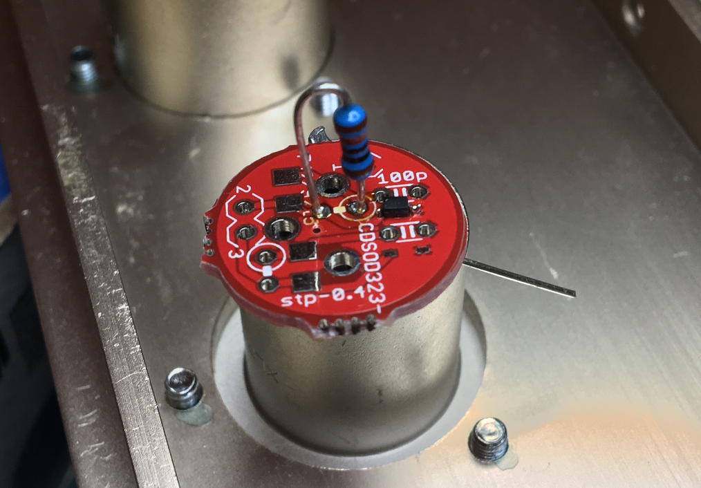
I just tested a Bourns CDSOD323-T12C-DSL low capacitance TVS diode. These are nice because they are pretty much optimal for directing surge currents and transients from signal lines to chassis pins instead of to supply lines. Most important, you can put them right next to the IO pins where they should be.

No one seems to be using these so I decided to tested one. Here's the test circuit:

Screenshot%2Bfrom%2B2019-01-08%2B17-13-59.png


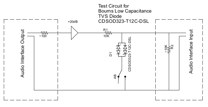
These diodes come in 12V and 24V. The one I tested is 12V only because I don't have an amplifier that can produce that much output. The 12V one clips at ~15V. So I put 12.5V (25 Vpp) into the above circuit and recorded the result using a typical AB measurement. Here are the results:

Screenshot%2Bfrom%2B2019-01-08%2B16-48-29.png


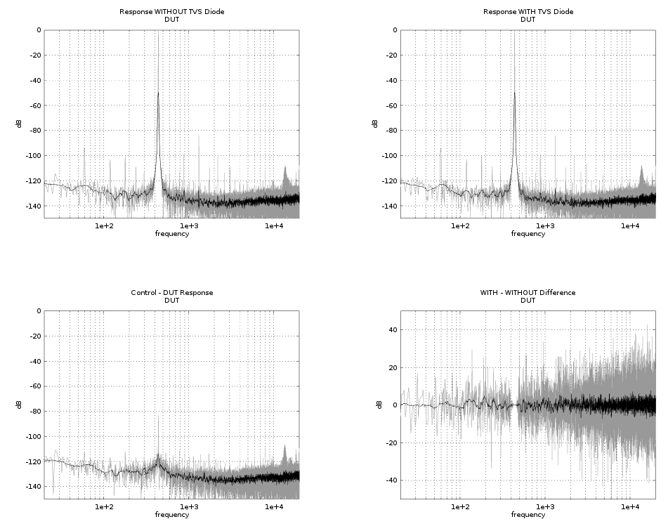
So the first two plots are A and B (with and without the TVS diode). The 3rd plot (lower left) is the spectrum of B - A and the final plot is the difference of the two spectrums.

The plots look noisy because of the high source impedance (10K) but the final plot shows pretty clearly that there is basically no difference between A and B other than expected differences due to noise.
 
TVS diodes work well as long as they are driven from a low impedance source. Any series impedance in the signal source will allow the diode to distort the signal, since the TVS shunt currents will be nonlinear, and this will become less important when the signal source impedance is low. With typical sources of around 0-50Ω, you can find small diodes whose distortion will be well below -160dB (as estimated by simulation). The 10K you use will cause extra distortion, but it'll be far less than your analyzer residual and maybe the residual of the amplifiers - it's all relative to  how clean everything else is and how clean you need it to be. Some commercial devices use absolutely huge conventional Si diode bridges on mike and line inputs, and that does not sound so good, so you can mess this up, and it has been messed up, if one tries hard enough.

If in doubt, rig up a simple simulation (exactly like your hardware measurement) with a voltage source, a series R and a shunt TVS to ground, and measure the gunk across the TVS. This will let you accurately see small problems like gunk around -160dBc or lower, just to have some confidence in the cleanliness of the clamps.
 
Mmmm I´m using this one 504-0402ESDA-MLP1 (mouser part number) and it has 60 times less capacitance, 3pf v/s 0.05pf. A 1n4148 have 4pf. What is the normal capacitance if 3pf is considered low?

best regards
Rafael
 
12afael said:
Mmmm I´m using this one 504-0402ESDA-MLP1 (mouser part number) and it has 60 times less capacitance, 3pf v/s 0.05pf. A 1n4148 have 4pf. What is the normal capacitance if 3pf is considered low?
Yeah, that is a nice part. At some point the capacitance is low enough that it doesn't matter to audio. Any distortion due to capacitance is going to be way out of range. And it doesn't look like there is any other kind of distortion [1]. Obviously people have been using conventional diodes for protection for a long time without issues and it looks like these are low capacitance because they have conventional diodes in series with the zeners. So performance should be at least similar. And in the case of this Bussmann part they look superior actually.

Note that the Bussmann part breakdown says 35V whereas the Bourns parts are around ~15V (for the 12V version) or probably ~35V (for the 24V version). But I don't suppose it matters unless the IO being protected doesn't have any protection at all (which would be strange) since TVS diodes are for catching the really bad transients and errant phontom power connections and such.

These are all a little small though. I was able to solder these without too much of a fuss (albeit a little sloppy in this particular case because I was only testing - I'm using the 24V ones):

TvsPcb.png


This pic is of the Bourns part which is 3mm. The Bussmann part you cite is 2mm. They do fit nicely on little PCBs like this however which is where they should be IMO.

[1] When actually clipping I can see massive switching noise. Meaning it looks like a typical clipped waveform but with lots of little spikes along the top. But of course we don't care about that.
 
I´m using them to protect the op amp output of a balanced line out. There is a cap and resistor to ground in between. Maybe it is not the best practice but it works well for 3000V with our ESD gun. I bet those caps look like Gruyere cheese hehe.
 
Even with a 1N4148 does 4pF really matter all that much for audio? If they are on ins and outs that 4pF will be swamped by the cable capacitance that gets connected.
 

Latest posts

Back
Top