


Bo Deadly
Well-known member
Can someone please explain this circuit to me? This is the tape drive control board of an early revision ReVox B77. IC1 is the controller and the triacs control AC to the motors. M1 is supply. M2 is take-up. I'm trying to understand how triac Q2 works:
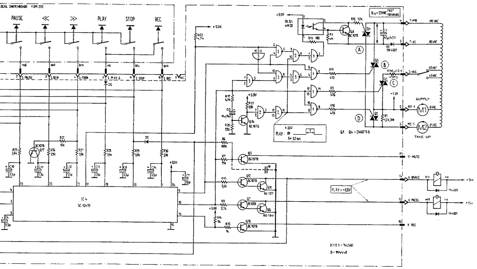
My current understanding (which must be incorrect) is that when transitioning to Play, IC1 controller pin 10 goes high, the gate of triac Q1 is driven low which turns it on (notice the triac reference level is 5V so pulling the gate down turns it on). Ok. But this also temporarily turns on transistor Q14 which, as you can see from the little window graphic, is supposed to make a 200ms pulse to temporarily turn on triac Q2 which bypasses R1 and gives the take-up reel a boost to get it moving.
Here's the part I don't understand. The gates are 74LS00 quad NAND gates (output always high unless both inputs are high in which case output goes low). So if you consider the 3 NAND gates between the transistor and Q2, in the steady state the transistor should be off > collector high > output of the first NAND gate low > output of the second NAND gate high. That doesn't match the graphic which shows the steady state low with a positive pulse.
What am I missing?