Circuit Simulation Help Please...

GroupDIY Audio Forum

Help Support GroupDIY Audio Forum:

This site may earn a commission from merchant affiliate links, including eBay, Amazon, and others.

ron_swanson

Well-known member
Joined
Nov 14, 2018
Messages
174
Location
San Francisco, USA
Hello,

I'm trying to better undertand the circuits I build, so as an exercise I tried building a virtual  copy of +-28VDC PSU that I recently built for fripholm's TG1 Zener project under Dynamic Processors elsewhere this forum to run in simulation. 

The physical circuit is working fine, but I'm unable to get that same circuit to work in a falstad simulator.  I believe I drew the circuit correctly, but I'm stumped why it doesn't seem to work virtually.  Maybe a wrong part selection or input / output choices? 

Anyone care to take a look to see what I may be missing?

Here's the link to the circuit I drew...
http://tinyurl.com/y56h6kj8

Original schematic attached.

Thanks in advance!

Greg
 

Attachments

  • TTx Zener TG PSU.pdf
    114.7 KB · Views: 27
Try simulating just the rectifier and smoothing caps and get that working first. Then add on the regulator. divide and conquer.

Cheers

Ian
 
I've never used this simulator, but there are opamp sympbols where you need to have the linear regulators. Clicking on it it shows a gain of 100000, so these seem to be actual opamps. If there are no regulators available: both LTSpice and Multisim are more sophisticated simulators that you can get for free.
 
Don't waste your time with an online simulator. They might be fine for really simple circuits for teaching maybe but I don't think it's going to be able handle a vaguely sophisticated circuit. And a voltage regulator is a sophisticated circuit. You cannot just put in an op amp. You can make a regulator out of an op amp, a voltage reference (like just a zener) and a pass transistor. But you cannot insert an op amp the way you have. That's just not how op amps work. Not even close. You would be much better off installing LTSpice and using proper LM317 / LM337 regulator models. And a lot of people here can tell you how to use LTSpice. Circuit simulation is a very important skill to know actually.
 
You have those opamps wired in a very strange manner.

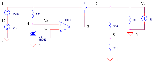
This is more like what a typical voltage regulator looks like:  one side of the opamp connects to a voltage reference, and then the feedback from the output is sampled via the other input.

image01.gif
 
As most of my projects start out on either breadboard or in LTSpice or a combination of both, I happen to have this power supply circuit as LTSpice file for you to play with :)

Rename ".txt" to ".asc" after downloading. Additionally to installing LTSpice you'll need to download and install "regulators.lib" which is needed for the LM3x7 regulators used here. Google it.
 

Attachments

  • psu_28.txt
    6.1 KB · Views: 2
fripholm said:
As most of my projects start out on either breadboard or in LTSpice or a combination of both, I happen to have this power supply circuit as LTSpice file for you to play with :)

Rename ".txt" to ".asc" after downloading. Additionally to installing LTSpice you'll need to download and install "regulators.lib" which is needed for the LM3x7 regulators used here. Google it.

Thanks to all for the input .

fripholm, I downloaded and installed LT Spice and found and installed the regulator.lib as you describe.  While your . asc (Thanks!) loads, I'm getting an error (notice?) saying the that '1N4007 is not recognized - using the default'.  Haven't been able to figure out how to fix that yet.  Maybe it doesn't matter?    Running a Mac in case that makes any matter. 

Cheers,
Greg

 
Just right click on it and pick a new diode of 1N4148. That's a small signal diode which would blow up in a power supply but for simulation it's fine. LTSpice doesn't come with a 1N400N models.
 
A Google search turned up this .model for the 1N4007: https://www.vishay.com/docs/88000/1n4007.txt

In general, LTspice will be a great simulation engine, but do not expect it to be loaded with every possible device.  To use this model, you want to add a SPICE .include statement to point to this file on your computer. Many manufacturers provide really detailed and accurate models for their components, and it's usually worth using them over a generic device.

There are also .subckt models that are used for more complex devices, such as op amps,  or more detailed models of passives etc. You can use those in LTspice by 1) opening the file on your computer from the LTspice file menu 2) scroll down to the line that contains the .subckt statement 3) right click on the name of the device 4) select "create device" from the popup menu that displays. A yellow box with connections attached to the node numbers is displayed, If their function is not labeled, you can 5) edit the name of the pins by rightclicking on them and renaming the pin with its function. If you do that, hti command-S to save the edited model, and you're all set. You can then add the model to your simulation - it appears in the "AutoGenerated" section of the list of components you can add.

If this is unclear, there are a zillion videos out there that will explain it in a different way.
 
Monte McGuire said:
If this is unclear, there are a zillion videos out there that will explain it in a different way.

This!

And I will add just another one ;)

Look up "standard.dio" and download this file. It contains hundreds of different diode models (1N400x included). Copy the file to your LTSpice documents folder ('...User/Documents/LTSpiceXVII/lib/cmp' on Windows, don't know on Mac) and re-start LTSpice.

Now, when you insert a standard diode and right click the symbol, you can choose your desired model from a list. These standard files also exist for BJTs (standard.bjt) and JFETs (standard.jft), MOSFETS,  etc. This way you don't have to make a symbol/device for every single model you find - at least not for simple parts like diodes and transistors.

HTH
 
Back
Top