Attenuators/pads and slight attenuation

GroupDIY Audio Forum

Help Support GroupDIY Audio Forum:

This site may earn a commission from merchant affiliate links, including eBay, Amazon, and others.

fazeka

Well-known member
Joined
Jun 3, 2004
Messages
1,186
Location
\/\//-\
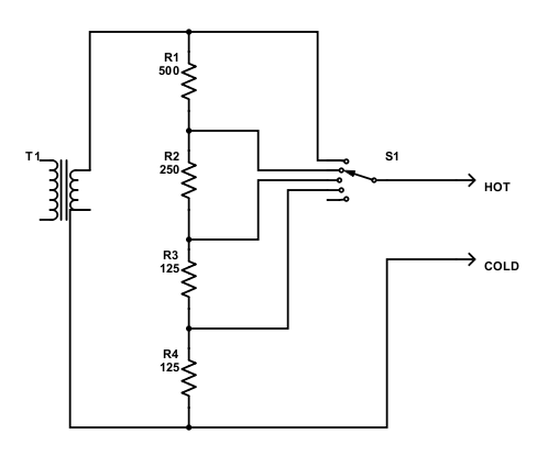
I want to build a U-pad on the outputs of some transformers (e.g., Triad HS-56, etc.) I want to use for "coloration".

Something like this:

https://www.gearslutz.com/board/showpost.php?p=13530784&postcount=23

https://www.gearslutz.com/board/showpost.php?p=13528362&postcount=17

from this thread: https://www.gearslutz.com/board/low-end-theory/1229726-low-end-techniques-tape-like-saturation-compression-hardware-software.html

The thing is, I know I could use a 1k dual ganged pot and be "close enough" but I like the steps a rotary switch provides. Not super-fine steps (was thinking something on order of 3-4dB) but more for easily matching if using on the two-buss.

While researching, I saw a comment posted on this forum (thread: https://groupdiy.com/index.php?topic=15577.0):

"In voltage systems (low source impedance, high load impedance), it's already impossible to build a resistive pad that has a small attenuation value without degrading either the input or the output impedance."

I saw something like this too on another forum (can't remember which...).

Wondering why that is? Intuitively (ignorantly, admittedly I am...), it seems like you would have degradation happening with large attenuation values, not small ones?

Can someone explain why?

Peace,
Chris
 
Because to get a small amount of attenuation your u-pad would have small input resistors and a large common resistor which means that the output impedance will be defined largely by the series input resistors which equates to slightly high output impedance and slightly low load impedance which is not good. A u-pad with large attenuation OTOH has large input resistors and a small common resistor which equates to low output impedance and high load impedance which is good. The real pickle is when you need medium attenuation where both the input and common resistor of the pad have to be about the same and yet not too small to load the source. Draw them out on paper and think about the source and load impedance of each step. Better still, use LTSpice and do impedance plots.

However, most modern gear has fairly low source impedance and relatively high load impedance which means that you can make something that would work well enough in most cases.  For example, if you use a u-pad of 150 ohm input resistors and a 1K common resistor, that will give you vaguely 3dB with an output impedance of ~250 ohms or so and a load impedance of ~650 ohms which is ok. Obviously we're not talking about precision engineering here. Just play with the values and experiment.
 
In addition to all squarewave says, when you look at the equations and you add the input/output impedance constraints, you see there are combinations that are plain impossible (requiring negative resistors!). The most common case of impossible solution is a 10dB mic attenuator.
 
abbey road d enfer said:
In addition to all squarewave says, when you look at the equations and you add the input/output impedance constraints, you see there are combinations that are plain impossible (requiring negative resistors!). The most common case of impossible solution is a 10dB mic attenuator.

To add to this, as a rough rule of thumb, it is impossible to make and attenuator whose attenuation is less than the ratio of the  input to output impedances. So in the mic pad example about, if the input impedance needs to remain 1K5 and the output impedance needs to be  150 ohms, the smallest attenuator you can make is 1500/150 = 10 = 20dB.

Cheers

Ian
 
Hi guys,

Sadly, I have been realizing what you guys have just said after a lot of reading, thought and messing with different resistances...  :(

But as sad as it is, I gained something out of the exercise. More knowledge!  ;D

So, I guess I could use a 1k dual-ganged pot... (think even Ian has suggested this in the past?). But...

I was really hoping to use rotary switches so I could better match in the case of using two channels on the 2-buss... you know, maybe something on order of 6dB steps (-6dB, -12dB, -18dB). I mean, -10dB already is quite a lot and is already not ideal/"impossible". Using pots I could be off a db or two trying to set them as pot tolerances are just not quite the same...

Is there another way?  :-\
 
fazeka said:
Is there another way?  :-\

As this is an attenuator after an output transformer then the answer is yes provided you are prepared to compromise on the final output impedance.  Just use a simple pot divider. The actual output impedance will then vary from very low (the impedance of the drive circuit reflected into the secondary) up to about one quarter of the total value of the pot.

Cheers

Ian
 
PRR said:
Anything you can do with a pot, you can do with switched resistors.

I was hoping so but I just don't have enough understanding yet to see how I can do that for small attenuation values (e.g., 3-6dB) without using small series resistors/large shunt resistor in a U-pad (as stated by squarewave above).
 
Actually you don't even need the u-pad. If I understand what you're doing (it is very possible that I do not), you want attenuation on the secondary of a transformer? If the source is a floating transformer winding, then you can just use a single-ended attenuator and the output will still be (almost) perfectly balanced. Meaning just do this:

revlog.gif


Your transformer secondary is Vin and the fully balanced output is Vout.

This is still balanced out because the transformer and attenuator network is a closed circuit. So any current that goes in one terminal must be matched by an equal and opposite current on the other terminal (AKA balanced).

And it's reverse log which is nicer because attenuation will be less in the fully CW end of rotation. If you don't want reverse log, drop the law bending resistor.
 
squarewave said:
Actually you don't even need the u-pad. If I understand what you're doing (it is very possible that I do not), you want attenuation on the secondary of a transformer?

Yes.

squarewave said:
If the source is a floating transformer winding, then you can just use a single-ended attenuator and the output will still be (almost) perfectly balanced. Meaning just do this:

revlog.gif


Your transformer secondary is Vin and the fully balanced output is Vout.

This is still balanced out because the transformer and attenuator network is a closed circuit. So any current that goes in one terminal must be matched by an equal and opposite current on the other terminal (AKA balanced).

And it's reverse log which is nicer because attenuation will be less in the fully CW end of rotation. If you don't want reverse log, drop the law bending resistor.

Interesting. Is it safe to assume, as to PRR's point, that I can use an L-pad (instead of a U-pad) to simulate this? So I can have a few steps of attenuation, something like -6dB, -12dB, -18dB?
 
Let's assume your transformer can drive a 1K load. The set of series wired resistors you need for switched attenuations of 6,12 and 18dB are:

Ouput-transformer-switched-attenuator.png


Cheers

Ian
 
Thanks Ian.

I'm still reading up on impedance. Go easy on me...  :eek:

I don't know if my transformers (e.g., Triad HS-56) can drive 1k but it seems they should be able to drive a lighter load such as 10k, which is from my understanding a typical minimum load impedance for modern gear. If so, do I change the resistors' amounts to 10x what you have listed in your diagram? Meaning, do those resistors need to match the load impedance?
 
fazeka said:
Thanks Ian.

I'm still reading up on impedance. Go easy on me...  :eek:

I don't know if my transformers (e.g., Triad HS-56) can drive 1k but it seems they should be able to drive a lighter load such as 10k, which is from my understanding a typical minimum load impedance for modern gear. If so, do I change the resistors' amounts to 10x what you have listed in your diagram? Meaning, do those resistors need to match the load impedance?

These days it is normal practice to use a brdging load i.e one that is 10 times larger than the driving (source) impedance. Hence 600 ohm outputs are typically fed into 10Ki inputs. If your transformer is a low impedance type (600 ohms say) then you should use an attenuator on its output that is close to that impedance (like 1K). The output impedance of this combination depends on the combined impedance of the transformer output and the attenuator but will most likely be less than 1K so it can safely be fed to a 10K bridging load.

Cheers

Ian
 
fazeka said:
I don't know if my transformers (e.g., Triad HS-56) can drive 1k
That's a jazzy transformer. That's the transformer on the input of a Pultec EQP-1A. Yes, it can easily drive 1K. It has taps for 600, 250, 150 and 62.5 ohms in / out. So you can do a lot more with that transformer than you think. Like use a two pole switch to make an attenuator on the input and simultaneously step down the secondary to get low output impedance.
 
Was thinking after reading squarewave's most recent post.

If I wire the HS-56 secondary as 150 ohms, wouldn't this be a 2:1 configuration? If so, would this mean I would incur a gain drop of 6dB?

If so, could I merely wire the secondary in different ways to incur an attenuation of sorts?

Secondary wired as 250 ohms would mean a drop of 3dB?

Secondary wired as 62.5 ohms would mean a drop of 9dB?
 
Go with Ian’s suggestion, hs56/66 will sound better with 1k across the secondary in my opinion.

/Johan
 
gurkan75 said:
Go with Ian’s suggestion, hs56/66 will sound better with 1k across the secondary in my opinion.

/Johan

This could be so. The transformer is liable to impart more colour if fed into a  load close to the expected value rather than a light load like a bridging input.

Cheers

Ian
 
ruffrecords said:
This could be so. The transformer is liable to impart more colour if fed into a  load close to the expected value rather than a light load like a bridging input.

Cheers

Ian
Most of the "colour" is due to the B-H curve. B and thus H do not change appreciably with load, unless it is so low as to significantly reduce the votages.
 
abbey road d enfer said:
Most of the "colour" is due to the B-H curve. B and thus H do not change appreciably with load, unless it is so low as to significantly reduce the votages.
This puzzles me since the magnetic field in the transformer, and hence the position of the B-H curve, depends on the current flowing which will be higher with a heavier load.

Cheers

Ian
 

Latest posts

Back
Top