What is the correct way to get 0v from a one winding toroidal?

GroupDIY Audio Forum

Help Support GroupDIY Audio Forum:

This site may earn a commission from merchant affiliate links, including eBay, Amazon, and others.
You can create a centre point for 0v by using 2 equal value resistors paralleled with some big caps strapped in series across the d.c  Maybe 100k with 1000uf.  Connect centre point to ground & you can thnk of it as 0v
 
Spencerleehorton said:
Hi All,

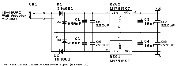
Need your advice on how to supply a 0v from only having a toroidal with one winding rather than the normal 2 windings giving you a centre tap 0v?
What are the options?
Hopefully it has at least two, a primary and secondary winding.  ;D

You can ground either end of a single secondary winding, then connect rectifier diodes to the free swinging end. The result is known as "half wave" rectification since, since supplies only get charged once per mains cycle (full-wave rectification charges 2x). 

JR

 
JR I’m talking about one winding (two wires) just so there is no confusion.

Before I attempt the picture of above txf by taking a feed off the ac to be 0v, could anyone else verify if this works correctly.

Btw The setup is 1 x 24v toroidal feeding pcb which gives 24v and 48v, I then want to add another pcb to supply +/- 15v.

Should I just take a 24v dc feed to 7815 and 7819 or should I try and take a feed from the AC to a new diode bridge?
I’m thinking I could take the +/- and the 0v and feed the other pcb rather than another diode bridge?
 
Spencerleehorton said:
Also advantages and disadvantages of half wave?

As apposed to full wave.
Half wave will have 2x the ripple voltage (capacitor sag between charges), so require larger capacitors for similar ripple performance,

Only advantage is cheaper.

JR
 
It doesn't matter. You RC just has to be 2x.

What VAC is the transformer secondary and what voltages do you want?

Note that a voltage doubler naturally makes a bipolar supply from a single secondary. So if your secondary is say 24VAC you could make +-15VDC after 2x filtering and regulation.
 
I’m not exactly sure what VAC the txf is but I suspect it is at least 20vac maybe 50vac, I will check.

Don’t quite understand what you put squarewave could you be a bit more specific please?
 
Like this:

power-inlet.png


But I probably shouldn't say "It doesn't matter" because this generally considered be clumsy. Using a proper center tapped secondary that can be full-wave-rectified is superior.
 
Ah ok well that’s perfect for the time being, I just want to get these api-553 eqs tested and I don’t have any spare Centre tapped txf!!
I’ll upgrade my Neve preamp with a centre tapped toroidal so I can do it properly and power both the Neve and the api correctly!!
 
They're both half-wave (they're almost certainly both the same exact circuit actually - they're just drawn a little differently). One half goes to charging pos, one half goes to charging neg. The only way to get full-wave is with a center tap.
 
Have taken out the negative side of the circuit and just getting the 7815 going and it’s failed again?

I’ve put in 1000uf then 100nf then the regulator then 10uf then 100nf.

Is it failing due to being 400uf down on the caps?
 

Latest posts

Back
Top