Using four 555 relay toggle circuits

GroupDIY Audio Forum

Help Support GroupDIY Audio Forum:

This site may earn a commission from merchant affiliate links, including eBay, Amazon, and others.

Rocinante

Well-known member
Joined
Jan 17, 2014
Messages
1,131
Location
Minnehopeless
I've been prototyping a monitor controller.
Ive been trying various micros as welll as teensy and arduinos for my in and out selection. So its 4 in and 4 out using momentary switches because they look pretty. 
Does anyone see any problem using four 555 relay toggle circuits similar to the one below but multiplied by 4, instead of say cd4043 into uln 2803?
I'm not so sure the part count is more or less, (it's probably less with the micros)
I tried Google. There are no 4 channel 555 circuits I could find.
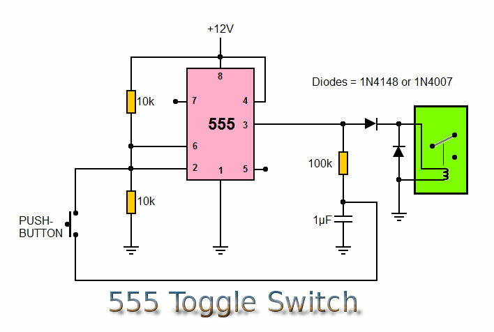
 
There is a 556 (dual 555) and even a 558 (quad 555) but the 558 does not have all of the pins of the 555.  https://en.wikipedia.org/wiki/555_timer_IC#556_dual_timer
 
I don't see why you would need a timer IC. You could just use a logic IC. Like a J-K flip flop like 74LS73 or whatever. Hold J and K high, trigger CLK and Q toggles. Although that is a really old IC. There are probably newer versions that are better and cheaper.

Although you will need a transistor drive because logic IC outputs are low voltage and low current.
 
squarewave said:
I don't see why you would need a timer IC. You could just use a logic IC. Like a J-K flip flop like 74LS73 or whatever. Hold J and K high, trigger CLK and Q toggles. Although that is a really old IC. There are probably newer versions that are better and cheaper.

Although you will need a transistor drive because logic IC outputs are low voltage and low current.
This works well on paper, but in the real world, contact bounce results in erratic behaviour. De-bouncing the contact is not a trivial task. I've pulled a few hairs trying to make a CD4013 do the job. The dual-inverter flip-flop worked much better; the only drawback is you need a non-grounded switch.
 
There are many ways to skin that cat, and any that delivers a good result is good. Personal preference can come down to familiarity with components, etc.

JR
 
Currently I am using a cd4043 into a uln2803. I should say 2 cd4043, one for 4 in and one for 4 out. The 2803 is an eight channel.
The problem there is I need the 4 outs to be able to be used at least 2 at a time for large studio speakers and nearfields.
I had been using an arduino/teensy but my coding skills kind of suck as I need 4 channels to be like radio buttons e.g. one at a time, and the 2 of the 4 outs to be able to used at the same time.
As I have it right now the radio buttons works fine but of the 4 out only the last channel is working.
I also just became really curious.
 
my coding skills kind of suck as I need 4 channels to be like radio buttons e.g. one at a time, and the 2 of the 4 outs to be able to used at the same time.
More seasoned coders may wag their fingers for suggesting this, but for me, starting out with an abundance of pins (40+ mega) when hacking out my first lines of nested/conditional logic simplified the learning process.
 
Oddly enough, I was just recently digging through paper pads from 25+ years ago looking for notes on this exact same sort of gizmo which I built to select "one or more" control room sets of speakers.  Alas, my stacks of legal pads are horribly disorganized. ***

But, this general design worked perfectly and was still in service as recently as a couple years ago.  If you pressed a momentary switch, that set of speakers would be selected and anything selected previously would be cleared.  Pressing 2/3/4/whatever momentaries would clear any previous selection(s) AND activate speaker pairs 2/3/4/whatever.

For each "speaker choice", I used a RS flip-flop (probably a pair of NAND gates).  I seem to recall using a diode from each switch into a bus to make an OR line, which triggered a short pulse-length monostable.  Output from the monostable was then bused to each of the reset inputs of all of the RS flip-flops.

So, pressing one or more momentaries created a result pulse to all R-S flippers, but the "chosen flip(s)" would still be engaged since the length of the "button down" was longer than the reset pulse feeding all flip flops.

RS flip flops have inherent debouncing, and were commonly used for tape transport controls.

Kinda crazy, but it worked perfectly for decades.  Each quad NAND package....good for two R-S/outputs.  I Tossed in another package of something for the monostable,

Hope that kinda makes sense....

Bri

***  I need to revert back to a paper system I used in the 1970's and 80's.  I would have a spiral bound 8.5 x 11" notebook (high school supply item) that I'd scribble in until it was filled, then begin a new one.  Old one would have the date range written on the cover and go into a file cabinet/whatever.  When I moved here in 2014, I found semi organized scribbles in date order covering maybe 20 years.
 
abbey road d enfer said:
You mean you want them interlocking (engaging one disengages the others)? How do you do that? Schematic please.

This one from Elliot Sound is a set reset. Pressing switch 2 for instance would reset 1, 3,  and 4. Follow it with a pc817 or uln2803.

As far as coding if you want I could put it here and it works good albeit my code is probably messy.
I have never compiled a PIC.

I asked about 555 as I have many. I also built a relay driver using pc817 but it still needed to be told what to do by the arduino.

As far as the teensy/arduino I guess I am realizing this is probably the best solution.  I know what I am coding isn't easy but I've built some involved Arduino projects, so it's not like I am going in blind. Still it's a lot of code.

Brian what chips did you use?
 
Rocinante said:
Brian what chips did you use?

I am 99% certain everything was 4xxx CMOS, but it might have been 74Cxxx CMOS.  Gizmo built in early 1990's with now-misplaced docs and my faulty memory!  lol

I think I've remembered the logic reset bus concept.  Diode on each button did a "pull down" onto the "a button has been pressed bus" into the monostable (which also did a power-up reset).

I attached a snap of the original user controller installed in the the Otari Concept desk.  It's the vertical row of illuminated pushbuttons installed into a blank desk panel.  Yes, six stereo monitor choices.

If I can attach another snap.....I transplanted the "logic" board into a 1 RU panel (with the  original audio switching in it's own box externally) when that studio retired the desk and moved into totally ProFools-land.

Bri


Attachments

  • IMG_0068.JPG
    IMG_0068.JPG
    815.6 KB
Well, the posting was the later ProFools install re-do of the UI.  Here should be a pic of the original switching in the Otari desk.

Bri
 

Attachments

  • IMG_0073.JPG
    IMG_0073.JPG
    1 MB
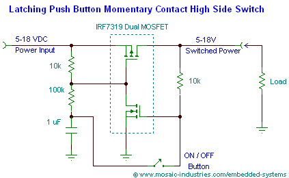
Here is the simplest toggle circuit I have found. It is a variation on the Soundcraft circuit. It can drive a relay directly.

latching-high-side-push-on-push-off-toggle-switch-circuit.png


Cheers

Ian
 
ruffrecords said:
Here is the simplest toggle circuit I have found. It is a variation on the Soundcraft circuit. It can drive a relay directly.

latching-high-side-push-on-push-off-toggle-switch-circuit.png


Cheers

Ian

Hello Ian!

But what about "radio pushbuttons"?  IE, selecting between multiple sources, or selecting multiple destinations....with a possibility of choosing two or more as a source or destination?  IOW., ability to lock down two "radio buttons" at the same time....activate two sets (or more) of speakers at the same time, yet clear all that mess out when a new choice is selected.

It can also be (seldom) useful as an input selection.

Bri

 
Brian Roth said:
But what about "radio pushbuttons"?  IE, selecting between multiple sources, or selecting multiple destinations....with a possibility of choosing two or more as a source or destination?  IOW., ability to lock down two "radio buttons" at the same time....activate two sets (or more) of speakers at the same time, yet clear all that mess out when a new choice is selected.
I did that many years ago, using either CD4001 or 4011-based latches (I don't remember). Each switch would also drive a bus via diodes and generated a pluse via a CR circuit; that would reset all latches. Making the discharge short enough ensured the Set instruction was dominant. Number of simultaneous selections was dependant on user's number of available fingers.
 
Hello Rocinante

If you want a micro to do this but not headache coding it, I suggest to use midibox, especially MB_NG software
It's an upper level event "programming",
just say this button do that to this output and forward value to this output etc...
with lot of event option, like banking (multilayer button) and radio group ....
At hardware  it's an STM32F4, with SRIO chain, simple 165 for button trig and 595 for output drive, usually direct LED but with ULN you can hook relay

Best
Zam
 

Latest posts

Back
Top