Trouble Shooting a Midland 13-601 (Level Loc Clone)

GroupDIY Audio Forum

Help Support GroupDIY Audio Forum:

This site may earn a commission from merchant affiliate links, including eBay, Amazon, and others.

EWalter

Active member
Joined
Sep 25, 2018
Messages
34
Location
Nashville
Hey Everyone,

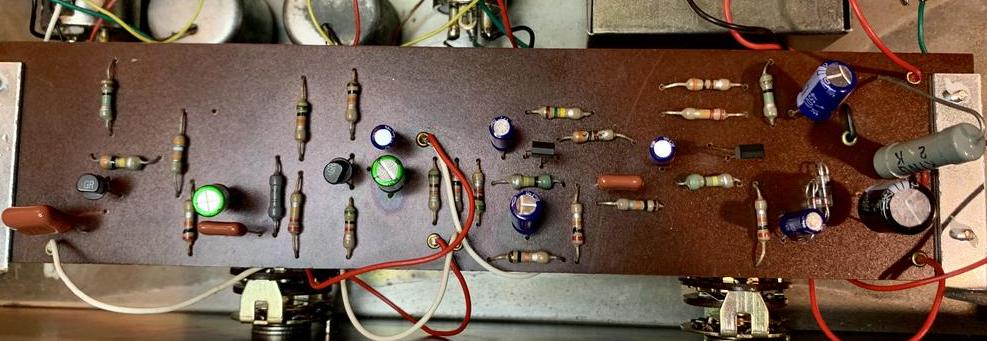
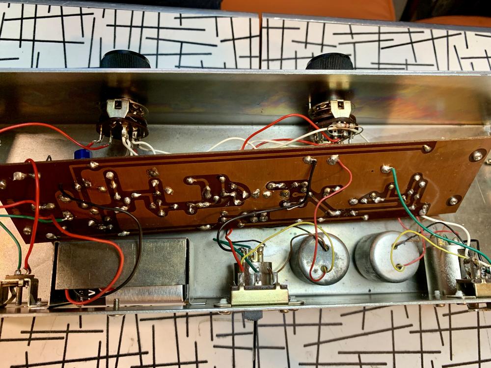
I'm working on this Midland Automatic Level Controller right now and could use some hive brain help. I can't find much of anything about these online. It's a pretty obvious rip off of the level loc, judging by the 6"/12"/18" distance markings on one of the pots and the look of the unit in general, however it doesn't follow the Level Loc schematic very closely.

Here are some photos: https://imgur.com/a/CHrVVL0

Problem: Unit passes signal in bypass but drops signal ~20dB when compressor is engaged and I don't hear any compression happening. I've completely recapped it and it is passing a little more signal now, but still not working correctly.

Similarly to the Level Lec, the bypass switch powers down the entire circuit and it becomes entirely passive, going through the input & output transformers. Unlike the Level Loc, the unit doesn't have an aux out, only xlr in & out, nor does it have an input pot.

I'm getting some interesting measurements that I wanted to share because I'm not exactly sure if what I'm finding is normal or not: When I send a 2v sine wave to the unit with the compression circuit engaged, I get 1v on the secondary of the input transformer. Once I switch the unit to bypass the secondary jumps up to 40v. I'm not sure if this is normal behavior and I'm curious if any of you can help to enlighten me. I understand that it might change given the load of the circuit, but this seems pretty drastic to me.

Additionally, when the unit is engaged, I'm measuring .01v on the output of the first capacitor (.1uF) in the circuit and it stays at the voltage all the way through the circuit. The cap is brand new and tested properly, but this seems like a big drop to me.

There are two transistors in the audio path that are both giving different readings on each of their legs. I switched these and they have the same readings each one was giving before at it's respective place in the circuit, so I don't think either one is bad. They also both tested out to be ok when I pulled them out of the circuit.

Any help would be much appreciated and apologies in advance for my ignorance - I'm certainly not anywhere near where I'd like to be with this type of work.

Cheers,
Erik
 
Without taking the pcb out and taking pictures of the component and track/solder side of the pcb not very much can be said.

What can be said is that there are only 4 transistors in total, 2 of them probably FET's (2SK30) and the other 2 maybe 2SC536.  I can't see any diodes.  So this unit has nothing to do with a Level-Loc.  It was probably intended as an accessory for CB-radio.

There are a lot of 10% resistors, so this unit has been made in the late 60's and the unit has already been tortured with a recap-job.  So nobody really knows what has been done to this unit additionally.

The power supply is also very simple, so nothing to expect from this unit.


analogguru said:
Without taking the pcb out and taking pictures of the component and track/solder side of the pcb not very much can be said.

What can be said is that there are only 4 transistors in total, 2 of them probably FET's (2SK30) and the other 2 maybe 2SC536.  I can't see any diodes.  So this unit has nothing to do with a Level-Loc.  It was probably intended as an accessory for CB-radio.

Interesting. I noticed the big difference in transistor count and wondered about that. It just looks like a level loc in so many ways that I thought I must sort of sound like one. I'll get some photos up asap - this project is sort of going on in the background of a few others. Do CB-radio accessories usually have xlr in/out?

analogguru said:
There are a lot of 10% resistors, so this unit has been made in the late 60's and the unit has already been tortured with a recap-job.  So nobody really knows what has been done to this unit additionally.

I hope I didn't torture it! I found that multiple caps were bad, so I went ahead and recapped the entire unit assuming that more could be bad or would be soon. Would you say this is bad practice? I've heard from many people that you might as well do the entire thing if you're already going in to change a few.

Cheers,
Erik
 
I'm finally getting back to working on this thing...

analogguru said:
Without taking the pcb out and taking pictures of the component and track/solder side of the pcb not very much can be said.

60pPNQx.jpg


5d57heC.jpg


I'm considering trying to replace the transistors, but having trouble figuring out what they are and cross-referencing. The two in the audio path have GR on top (as you see in the picture), and T K17 on the side.

The ones in the PSU are C458 which seem to be a little easier to find. However, both of these are measuring the same and I'm not sure if they're the problem. they both read ~6v on one leg, ~3v on the middle leg, and ~.03v on the last leg.


If I send a 1v sine wave to this guy, I get about 1v out in bypass ("Direct") which is going through both transformers, but as soon as I take it out of bypass ("Automatic"), it drops down to .01v at the output of the first cap in the signal path and stays there all the way through. This is a brand new 100nF cap and I've actually taken it out of the circuit completely and still get the same result, so I'm assuming the transistor is dragging signal down somewhere, but I don't really know how to test transistors. I've pulled both of the ones in the audio path and tested resistances between legs, and both give the same readings - I'm sure this isn't very thorough... I even swapped the position of both of them and I'm getting the exact same readings everywhere  :eek:

Any tips would be much appreciated!

Cheers,
Erik
 
I keep coming back to this box in my free time to try to get it going. I'll post an update here in case anyone has any ideas.

One new thing I noticed is that it's passing low frequency better than anything else. I'm still not hearing a compressor kick in, but it a bass comes through much better than a vocal. On a linear analysis, I'm seeing a huge bandpass with a center frequency around 500Hz when the "Automatic" setting is engaged.

I'm testing signal on the Transistors (#1 being the furthest to the left side of the board) in the audio path and getting the following measurements:

Transistor 1:
Leg1: 3.4VDC
Leg2 (Center): ~1VDC (this jumps around a lot)
Leg3: 3.4VDC

Transistor 2:
Leg1: 4.1VDC
Leg2 (Center): .8VDC
Leg3: 2.2VDC


Power supply Transistors (#1 is furthest to the right of the PCB) measurements are below:

PSU Transistor 1:
Leg1: .08VDC
Leg2 (Center): 2.9VDC
Leg3: .69VDC

PSU Transistor 2:
Leg1: .08VDC
Leg2 (Center): 3.3VDC
Leg3: .68VDC


EWalter said:
I keep coming back to this box in my free time to try to get it going. I'll post an update here in case anyone has any ideas.

One new thing I noticed is that it's passing low frequency better than anything else. I'm still not hearing a compressor kick in, but it a bass comes through much better than a vocal. On a linear analysis, I'm seeing a huge bandpass with a center frequency around 500Hz when the "Automatic" setting is engaged.

I'm testing signal on the Transistors (#1 being the furthest to the left side of the board) in the audio path and getting the following measurements:

Transistor 1:
Leg1: 3.4VDC
Leg2 (Center): ~1VDC (this jumps around a lot)
Leg3: 3.4VDC

Transistor 2:
Leg1: 4.1VDC
Leg2 (Center): .8VDC
Leg3: 2.2VDC


Power supply Transistors (#1 is furthest to the right of the PCB) measurements are below:

PSU Transistor 1:
Leg1: .08VDC
Leg2 (Center): 2.9VDC
Leg3: .69VDC

PSU Transistor 2:
Leg1: .08VDC
Leg2 (Center): 3.3VDC
Leg3: .68VDC

Probably be useful if you looked up the transistors & quoted the voltages against the bass, emitter, & collector for each one.  After all anyone helping you will have to do this & since we don't even know what the transistors are it's difficult.
 
Rob Flinn said:
Probably be useful if you looked up the transistors & quoted the voltages against the bass, emitter, & collector for each one.  After all anyone helping you will have to do this & since we don't even know what the transistors are it's difficult.

Sorry for the delay here, this one got a little lost in the shuffle.

I think I may have posted this earlier in the thread, so for give me for leaving it out of my last post, but I'm not really sure what the transistors are. The two in the audio path have a "GR" on top and "TK17" on the side.  I'm having trouble finding anything about these.

The two in the power supply have "C458" on them. I had trouble finding anything that cross references for these as well. It looks like there are some similar ones found in some hifi amps.


I did some work on this thing and had some success. I realized that a couple of the new caps I replaced were not polarized :FACEPALM:... It's working now though - compressing violently and actually sounds a bit like a level-loc. The issue I'm still having is that it's super low output. I found that it needs to go into a mic pre (similar to Level Loc), but even with a ~60dB gain mic pre wide open it's still very low level signal.

I'm not sure if this could be solved by replacing the transistors or if that is even something I should consider. I also wonder if a different transformer with a higher winding ratio might step it up a bit. I'm assuming not enough though...

Any thoughts would be much appreciated!

Cheers,
Erik
 
> have "C458" on them. I had trouble finding anything

Japanese transistors start "2SC". The "2S" is omitted on small parts.

2SC458 is, as expected, a plain jellybean part, nothing special. Use 2N3904. _IF_ they are truly dead (unlikely).
http://rtellason.com/transdata/2sc458.pdf
 

Latest posts

Back
Top